Connections, indicators, configuration switches
106377_en_04 PHOENIX CONTACT 13 / 68
For additional information, please refer to “Flow charts for the charging process” on
page 47.
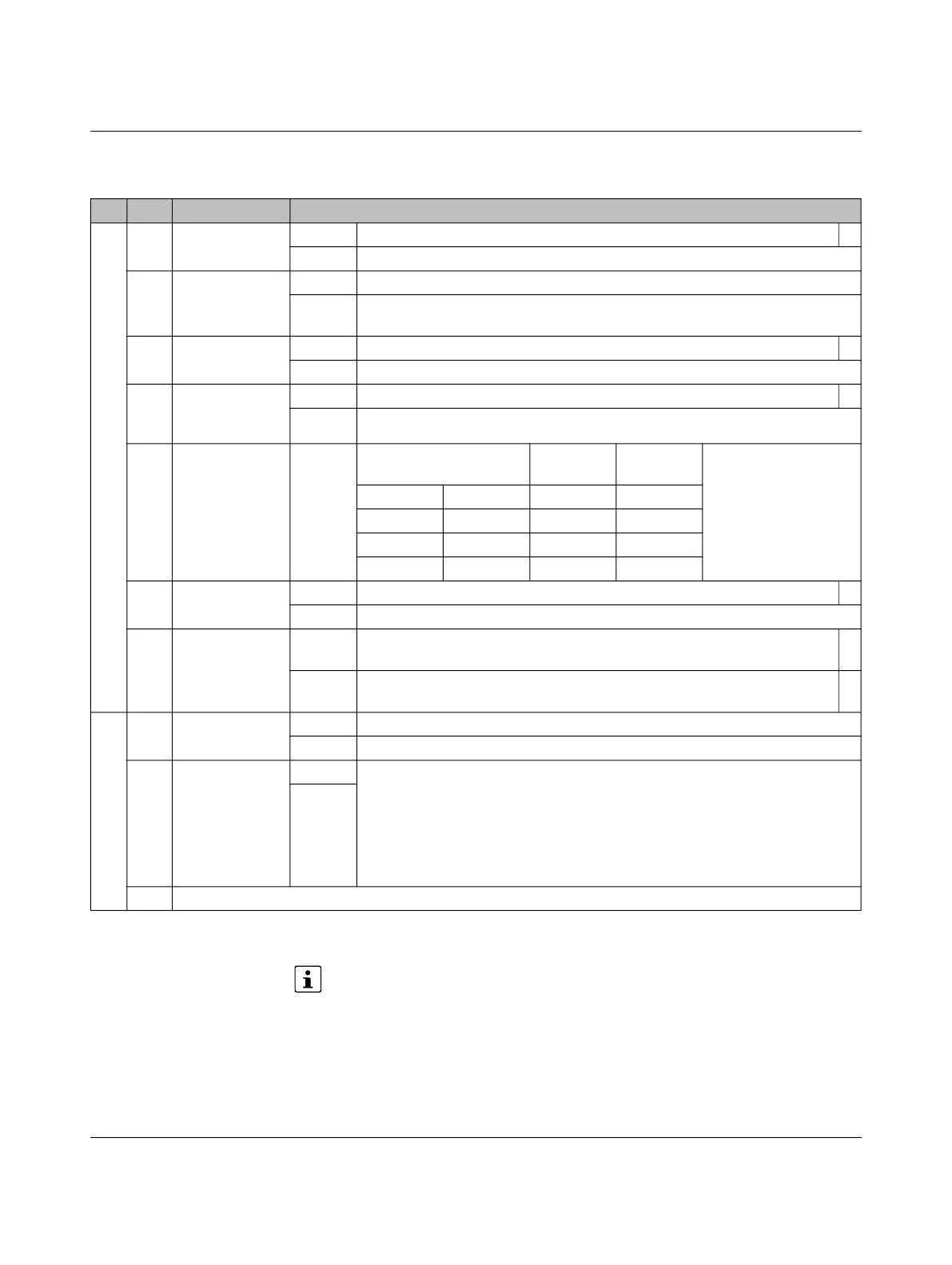
Table 2-3 Configuration switches S1 + S2
No. DIP Name Description
S1 1 Connection,
case B/C
ON Charging station with vehicle connector (case C) *
OFF Charging station with infrastructure socket outlet (case B)
2 XR evaluation ON XR input is evaluated, XR = 0 status F
OFF XR input is not evaluated or XR input is evaluated in a modified way according
to Modbus register 4011
3 Locking function ON Connection locking upon signal at digital input ML, can be configured *
OFF Connection locking at status B
4 Evaluation of
13 A charging
cable
ON 13 A charging cable is not permissible *
OFF 13 A charging cable is permissible
5 + 6 Default setting
for charging cur-
rent
Depending on digital
input CCR
CCR = 0 CCR = 1
5 = OFF 6 = OFF 16 A 8 A
5 = OFF 6 = ON 20 A 10 A
5 = ON 6 = OFF 32 A 13 A
5 = ON 6 = ON 63 A 20 A
7 Evaluation of
Proximity Plug
ON Evaluation according to GB/T 18487.1 *
OFF Evaluation according to IEC 61851-1
8 Optional
locking
ON No locking of the charging connector and evaluation of the locking confirma-
tion LD1/LD2
*
OFF Locking of the charging connector and evaluation of the locking confirma-
tion LD1/LD2
*
S2 1 Baud rate ON 19200
OFF 9600
2 - 6 Modbus
address
ON = 1 0, 0, 0, 0, 1 = Modbus address 1
0, 0, 0, 1, 0 = Modbus address 2
…
1, 1, 1, 1, 0 = Modbus address 30
1, 1, 1, 1, 1 = reserved
OFF = 0
7 + 8 Reserved for future expansions
*
Not for EV-CC-AC1-M3-CC-...

 Loading...


