4
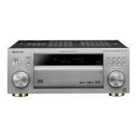
VSX-1020-K
1
2 3 4
A
B
C
D
E
F
1
2 3 4
CONTENTS
SAFETY INFORMATION ..........................................................................................................................................................2
1. SERVICE PRECAUTIONS ....................................................................................................................................................5
1.1 NOTES ON SOLDERING ...............................................................................................................................................5
1.2 NOTES ON REPLACING PARTS ...................................................................................................................................5
1.3 CAUTION ........................................................................................................................................................................5
2. SPECIFICATIONS .................................................................................................................................................................6
2.1 SPECIFICATIONS...........................................................................................................................................................6
2.2 PANEL FACILITIES .........................................................................................................................................................7
3. BASIC ITEMS FOR SERVICE.............................................................................................................................................11
3.1 CHECK POINTS AFTER SERVICING..........................................................................................................................11
3.2 PCB LOCATIONS .........................................................................................................................................................12
3.3 JIGS LIST......................................................................................................................................................................13
4. BLOCK DIAGRAM...............................................................................................................................................................14
4.1 OVERALL WIRING DIAGRAM......................................................................................................................................14
4.2 DIGITAL AUDIO BLOCK DIAGRAM..............................................................................................................................16
4.3 ANALOG AUDIO BLOCK DIAGRAM ............................................................................................................................18
4.4 DIGITAL VIDEO BLOCK DIAGRAM..............................................................................................................................19
4.5 ANALOG VIDEO BLOCK DIAGRAM ............................................................................................................................20
4.6 GND BLOCK DIAGRAM ...............................................................................................................................................22
5. DIAGNOSIS.........................................................................................................................................................................25
5.1 DIAGNOSIS FLOWCHART...........................................................................................................................................25
5.2 ERROR INDICATIONS..................................................................................................................................................40
6. SERVICE MODE .................................................................................................................................................................41
6.1 TEST MODE .................................................................................................................................................................41
7. DISASSEMBLY....................................................................................................................................................................43
8. EACH SETTING AND ADJUSTMENT ................................................................................................................................50
8.1 HOW TO UPDATE FIRMWARE ....................................................................................................................................50
8.2 IDLE CURRENT ADJUSTMENT ..................................................................................................................................53
9. EXPLODED VIEWS AND P
ARTS LIST ...............................................................................................................................54
9.1 PACKING SECTION......................................................................................................................................................54
9.2 EXTERIOR SECTION...................................................................................................................................................56
10. SCHEMATIC DIAGRAM ....................................................................................................................................................60
10.1 AUDIO ASSY ..............................................................................................................................................................60
10.2 COMPONENT ASSY ..................................................................................................................................................62
10.3 COMPOSITE, MIC, F-VIDEO and BRIDGE2 ASSYS.................................................................................................64
10.4 F-HDMI, USB MTG and HDMI MTG ASSYS ..............................................................................................................66
10.5 AMP ASSY..................................................................................................................................................................68
10.6 DISPLAY, HEADPHONE and POWER SW ASSYS....................................................................................................70
10.7 D-MAIN ASSY (1/12) ..................................................................................................................................................72
10.8 D-MAIN ASSY (2/12) ..................................................................................................................................................78
10.9 D-MAIN ASSY (3/12) ..................................................................................................................................................80
10.10 D-MAIN ASSY (4/12) ................................................................................................................................................82
10.11 D-MAIN ASSY
(5/12) ................................................................................................................................................84
10.12 D-MAIN ASSY (6/12) ................................................................................................................................................86
10.13 D-MAIN ASSY (7/12) ................................................................................................................................................88
10.14 D-MAIN ASSY (8/12) ................................................................................................................................................90
10.15 D-MAIN ASSY (9/12) ................................................................................................................................................92
10.16 D-MAIN ASSY (10/12) ..............................................................................................................................................94
10.17 D-MAIN ASSY (11/12) ..............................................................................................................................................96
10.18 D-MAIN ASSY (12/12) ..............................................................................................................................................98
10.19 MAIN and BRIDGE1 ASSYS ..................................................................................................................................100
11. PCB CONNECTION DIAGRAM ......................................................................................................................................102
11.1 AUDIO ASSY ............................................................................................................................................................102
11.2 COMPONENT ASSY
................................................................................................................................................104
11.3 COMPOSITE, MIC, F-VIDEO and BRIDGE2 ASSYS...............................................................................................106
11.4 F-HDMI, USB MTG and HDMI MTG ASSYS ............................................................................................................108
11.5 AMP ASSY................................................................................................................................................................110
11.6 DISPLAY, HEADPHONE and POWER SW ASSYS..................................................................................................114
11.7 D-MAIN ASSY...........................................................................................................................................................118
11.8 MAIN ASSY...............................................................................................................................................................122
11.9 BRIDGE1, GUIDE3 GIUIDE-L and GUIDE-R ASSYS ..............................................................................................126
12. PCB PARTS LIST ............................................................................................................................................................128

 Loading...
