20
WARRANTY
CENTER
C
E
R
T
I
F
I
E
D
PROGRAMMING:
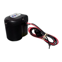
STEP 1 Press and hold the PROGRAM button on the top of the HPU for three seconds. The LED will turn solid
GREEN. FIG 1
STEP 2 Press and release the DOWN button on the Remote. The GREEN LED on the HPU will turn off, beep,
and then return to flashing once per second indicating the pairing has been completed.
STEP 3 Test functionality by following the OPERATION Section.
NOTE: If dual units are installed, repeat STEPS 1-3 for the other HPU. Up to ten (10) wireless controllers can be
programmed to each unit.
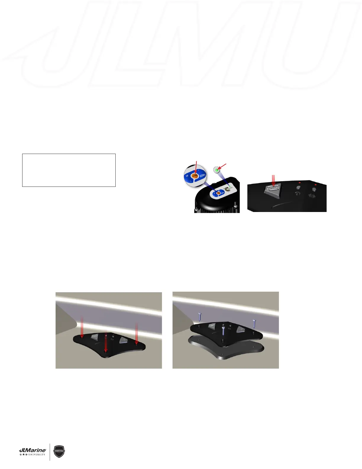
INSTALLATION:
STEP 1 Locate an area with a flat surface to mount the
Foot Switch.
STEP 2 Remove the Foot Switch from its rubber pad and
hold it in the desired location. Use a fine point
marker to mark Mounting Screw locations. FIG 3
WARNING: Before drilling Pilot Holes, inspect the area beneath the mounting surface to ensure that the Drill Bit
will not cause any damage.
STEP 3 Using a 7/64” Drill Bit, drill holes in the previously marked locations.
STEP 4 Place the Foot Switch back into its rubber pad, and fasten both the Switch and pad to the vessel using a
#2 Phillips-Head Screwdriver and the three #6 x 3/4” Pan-Head Screws. FIG 4
Installation Instructions
Changing the Battery
Programming Instructions
Congratulations on your purchase of an Advanced Foot Switch featuring
state-of-the-art C-Monster Control System technology.
Installation
Step 1 Locate a suitable area with a flat surface to mount the foot switch.
Step 2 Remove the foot switch from its rubber pad, and hold it in the desired
location. Use a fine point marker to inscribe the intended mounting
screw locations. (See Figure 1)
WARNING – Before drilling pilot holes for the foot switch mounting screws,
inspect the area beneath the mounting surface in order to ensure
that the drill bit will not cause any damage.
Step 3 Using the 7/64” drill bit, carefully drill holes in the previously
inscribed location.
Step 4 Place the foot switch back into its rubber pad, and fasten both the
switch and pad to the vessel using a #2 Phillips-head screwdriver
and the (3) #6 x 3/4” pan head screws. (See Figure 2)
Changing the Battery
Step 1 Remove the (3) #6 x 3/4” pan head screws with a #2 Phillips-head
screwdriver, and remove the foot switch and its rubber base from
the vessel’s surface.
Step 2 Take the foot switch and its base
to a dry location, and separate the
foot switch and rubber base.
Step 3 Thoroughly dry the foot switch and
then remove the (7) screws on its
underside with a #1 Phillips-head
screwdriver. (See Figure 1)
Step 4 With the screws removed, life the cover off of the switch, and
carefully remove the circuit board.
Step 5 Replace the battery with any CR2032 3V Lithium Coin Battery.
Step 6 Inspect the inside of the foot switch case thoroughly for signs of
moisture as well as damage to the rubber seals. If the rubber seals
appear to be damaged, or of a substantial amount of moisture is
found, please contact a member of our technical support staff.
[(813) 689-9932 option 2]
NOTE: If needed, a hair dryer may be used to dry residual moisture in
the foot switch case.
Step 7 Assemble and install the foot switch in the reverse order.
Programming
Step 1 Locate the “program” button on the top of the pump unit, depress
and hold it for 3 seconds until the LED steadily illuminates green in
color. The pump unit is now ready to be paired with a foot switch.
(See Figure 1)
NOTE: When dual Power-Pole shallow water anchors are installed,
this procedure should be performed on BOTH pump units.
Step 2 Next, depress and release either the “up” or the “down” button on
the foot switch 1 time. The green LED on the pump unit will initially
turn off, and then it will return to flashing once per second, this will
indicate that the pairing has been completed. (See Figure 2)
Step 3 The foot switch is now paired to the pump unit. Test its functionality
with both the “up” and the “down” buttons to ensure that the pairing
procedure was completed successfully.
Advanced Foot Switch
Featuring Technology
IMPORTANT!
REGISTER YOUR NEW ADVANCED FOOT SWITCH
To validate your warranty, register your new product online at www.power-pole.com
or ll out and submit this registration card.
Name ______________________________________________________________________
Address _____________________________________________________________________
City _____________________________________ State _________ Zip ______________
Email address ________________________________________________________________
Date of purchase __________________________________________ Age ______________
Place of purchase ______________________________________________________________
Type of boat ___________________________________________ Length ______________
I have read and understand the warranty of this product.
Signature ____________________________________________________________________
Figure 1 Figure 2
Figure 1
Figure 1 Figure 2
Hydraulic Pump Unit (HPU)
Figure 1
LED
PROGRAM button
Installation Instructions
Changing the Battery
Programming Instructions
Congratulations on your purchase of an Advanced Foot Switch featuring
state-of-the-art C-Monster Control System technology.
Installation
Step 1 Locate a suitable area with a flat surface to mount the foot switch.
Step 2 Remove the foot switch from its rubber pad, and hold it in the desired
location. Use a fine point marker to inscribe the intended mounting
screw locations. (See Figure 1)
WARNING – Before drilling pilot holes for the foot switch mounting screws,
inspect the area beneath the mounting surface in order to ensure
that the drill bit will not cause any damage.
Step 3 Using the 7/64” drill bit, carefully drill holes in the previously
inscribed location.
Step 4 Place the foot switch back into its rubber pad, and fasten both the
switch and pad to the vessel using a #2 Phillips-head screwdriver
and the (3) #6 x 3/4” pan head screws. (See Figure 2)
Changing the Battery
Step 1 Remove the (3) #6 x 3/4” pan head screws with a #2 Phillips-head
screwdriver, and remove the foot switch and its rubber base from
the vessel’s surface.
Step 2 Take the foot switch and its base
to a dry location, and separate the
foot switch and rubber base.
Step 3 Thoroughly dry the foot switch and
then remove the (7) screws on its
underside with a #1 Phillips-head
screwdriver. (See Figure 1)
Step 4 With the screws removed, life the cover off of the switch, and
carefully remove the circuit board.
Step 5 Replace the battery with any CR2032 3V Lithium Coin Battery.
Step 6 Inspect the inside of the foot switch case thoroughly for signs of
moisture as well as damage to the rubber seals. If the rubber seals
appear to be damaged, or of a substantial amount of moisture is
found, please contact a member of our technical support staff.
[(813) 689-9932 option 2]
NOTE: If needed, a hair dryer may be used to dry residual moisture in
the foot switch case.
Step 7 Assemble and install the foot switch in the reverse order.
Programming
Step 1 Locate the “program” button on the top of the pump unit, depress
and hold it for 3 seconds until the LED steadily illuminates green in
color. The pump unit is now ready to be paired with a foot switch.
(See Figure 1)
NOTE: When dual Power-Pole shallow water anchors are installed,
this procedure should be performed on BOTH pump units.
Step 2 Next, depress and release either the “up” or the “down” button on
the foot switch 1 time. The green LED on the pump unit will initially
turn off, and then it will return to flashing once per second, this will
indicate that the pairing has been completed. (See Figure 2)
Step 3 The foot switch is now paired to the pump unit. Test its functionality
with both the “up” and the “down” buttons to ensure that the pairing
procedure was completed successfully.
Advanced Foot Switch
Featuring Technology
IMPORTANT!
REGISTER YOUR NEW ADVANCED FOOT SWITCH
To validate your warranty, register your new product online at www.power-pole.com
or ll out and submit this registration card.
Name ______________________________________________________________________
Address _____________________________________________________________________
City _____________________________________ State _________ Zip ______________
Email address ________________________________________________________________
Date of purchase __________________________________________ Age ______________
Place of purchase ______________________________________________________________
Type of boat ___________________________________________ Length ______________
I have read and understand the warranty of this product.
Signature ____________________________________________________________________
Figure 1 Figure 2
Figure 1
Figure 1 Figure 2
Figure 2
Figure 3 Figure 4
SECTION 1.9 – Electronics & Controllers
C-Monster Controller Programming & Operation
Advanced Foot Switch
INSTALLATION TOOLS:
• 7/764” Drill Bit
• #2 Phillips Screw Driver
 Loading...