8
WARRANTY
CENTER
C
E
R
T
I
F
I
E
D
SECTION 1.5 – Electronics & Controllers
C-Monster 1.0 Circuit Board Installation
REMOVAL:
STEP 1 Disconnect the RED 12V (+) wire from the Battery Source or remove the Inline Fuse.
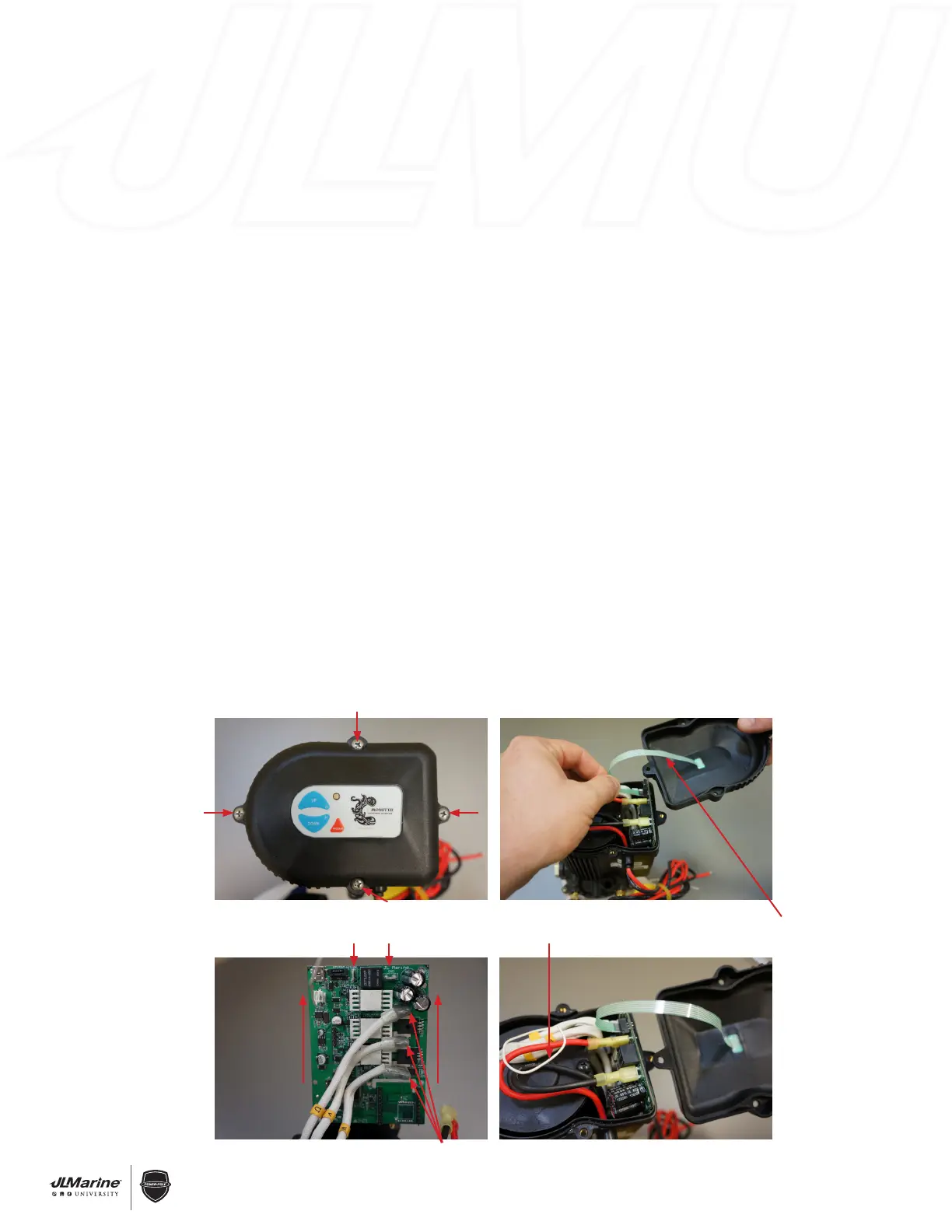
STEP 2 Remove the Motor Cover by unscrewing the four Phillips Head Bolts that attach the Cover to the Motor
Assembly. FIG 1
STEP 3 Gently pull the Membrane Switch Ribbon Wire to disconnect it from the Circuit Board. FIG 2
STEP 4 Disconnect the RED 12V (+) and BLACK 12V (-) wires from the Circuit Board.
STEP 5 Grab the sides of the Circuit Board and carefully slide it upward out of the Motor Assembly. FIG 3
STEP 6 Disconnect the three Brushless Motor Wires.
NOTE: The Brushless Motor Wires are labeled “U”, “V”, and “W.” These letters correspond to labels on the
Circuit Board. FIG 3
INSTALLATION:
STEP 1 Follow REMOVAL STEPS 3-6 in reverse order to reconnect wiring.
IMPORTANT! Ensure that the Brushless Motor Wires and the 12V Wires are connected to the proper terminals
on the new Circuit Board.
STEP 3 Route the white Antenna Wire as shown in FIG 4.
WARNING! Improper wiring will result in signal interference.
STEP 5 Reinstall the Cover with the four Phillips Head Bolts.
STEP 6 Reconnect the RED 12V (+) wire to the Battery Source, or re-install the Inline Fuse.
STEP 7 Program the new Circuit Board. Section 1.9 C-Monster Top Side Controls
Figure 1
Figure 3
Figure 2
Figure 4
Negative and positive terminals
Brushless Motor Wires
Antenna Wire
Membrane Switch
Ribbon Wire
 Loading...