24
WARRANTY
CENTER
C
E
R
T
I
F
I
E
D
Figure 3C
CLICK
SECTION 1.10 – Electronics & Controllers
C-Monster Controller Battery Replacement
ADVANCED KEY FOB, CM1 OR CM2 REMOTE CONTROL KEY FOB:
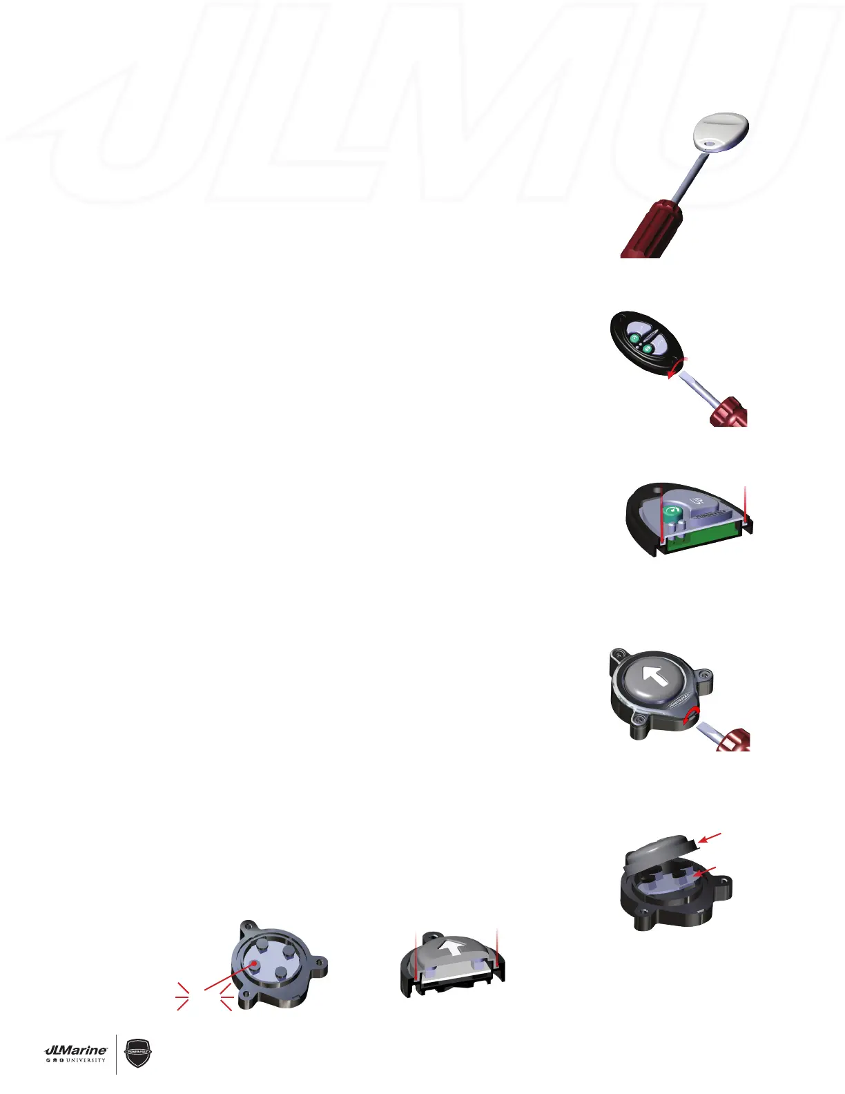
STEP 1 Ensure the surrounding area is dry to avoid moisture intrusion.
STEP 2 Use a small flat-blade Screwdriver to remove the top Cover for the Remote Control
Key Fob. FIG 1
STEP 3 Remove the Rubber Switch Membrane and the Board from the Bottom Cover.
STEP 4 Remove the Battery from the Holder on the front of the Board and replace with
any CR2032 3V Lithium Coin Battery.
STEP 5 Place the Board and Rubber Switch Membrane back into the Bottom Cover and
ensure that the Rubber Switch Membrane is seated properly prior to installing
the Top Cover.
ADVANCED SURFACE MOUNT REMOTE CONTROL:
STEP 1 Ensure the surrounding area is dry to avoid moisture intrusion.
STEP 2 Remove the two #8 x 3/4” slotted Screws from the top of the Dash Switch.
STEP 3 Use a small flat-blade Screwdriver to remove the Dash Switch Cover Plate. FIG 2A
STEP 4 Remove the Rubber Switch Membrane and the board from the Dash Switch Base.
STEP 5 Remove the Battery from the Holder on the back of the Board and replace with any
CR2032 3V Lithium Coin Battery.
STEP 6 Place the Board and Rubber Switch Membrane back into the Dash Switch Base and
ensure that the Rubber Switch Membrane is seated properly prior to installing the
Cover Plate. FIG 2B
CM1 OR CM2 WIRELESS FOOT SWITCHES:
STEP 1 Remove the three Screws with a #2 Phillips-Head Screwdriver.
STEP 2 Take the Foot Switch and its base to a dry location, and separate the Foot Switch
and Rubber Base using a small flat-blade screwdriver FIG 3A
STEP 3 Remove the Rubber Switch Membrane and the Circuit Board from the Foot Switch
Base. FIG 3B
STEP 4 Remove the Battery from the Holder on the back of the Circuit Board and replace
with any CR2032 3V Lithium Coin Battery.
STEP 5 Inspect the inside of the Foot Switch case thoroughly for signs of moisture as well
as damage to the Rubber Seals. If the Rubber Seals appear to be damaged, or a
substantial amount of moisture is found, please contact a member of our Customer
Service Team. (813-689-9932 option 2)
STEP 6 Place the Circuit Board back into its Base with Circuit Board Level and
small Black Caps placed over each Circuit Board Button. FIG 3C
NOTE: Each small Black Cap should push down and come up when released. If the Black
Cap does not push down remove Black Cap and rotate 1 quarter turn and
re-install.
STEP 7 Install the Rubber Switch Membrane back into the Foot Switch Base and ensure
that the Rubber Switch Membrane is seated properly prior to installing the Cover.
FIG 3D
Figure 2B
Figure 1
Figure 2A
Figure 3A
Figure 3B
Switch Cover
Circuit Board
Figure 3D
 Loading...