33
WARRANTY
CENTER
C
E
R
T
I
F
I
E
D
1
55//1166”” CCoommpprreessssiioonn FFiittttiinnggss IInnssttrruuccttiioonnss
IImmppoorrttaanntt:: TThhee hhyyddrraauulliicc ttuubbiinngg wwiillll nneeeedd ttoo bbee rroouutteedd tthhrroouugghh tthhee rruubbbbeerr ggrroommmmeett iinn tthhee uuppppeerr UU--CChhaannnneell aanndd
aattttaacchheedd ttoo tthhee hhyyddrraauulliicc ccyylliinnddeerr vviiaa tthhee ccoommpprreessssiioonn ffiittttiinnggss pprriioorr ttoo iinnssttaalllliinngg tthhee ccyy
lliinnddeerr..
Route the hydraulic tubing according to the instructions in the “Owner’s Manual”. If using the supplied thru-hull
bushings, be sure to use an 11/32” drill bit instead of a 5/16” bit.
SStteepp 11:: HHyyddrraauulliicc ccyylliinnddeerr ffiittttiinnggss
A. With the tubing routed to the cylinder, pull enough slack such that the blue tubing reaches the uppermost
compression fitting (blue dust cap) and the black tubing reaches the lower compression fitting (black dust cap).
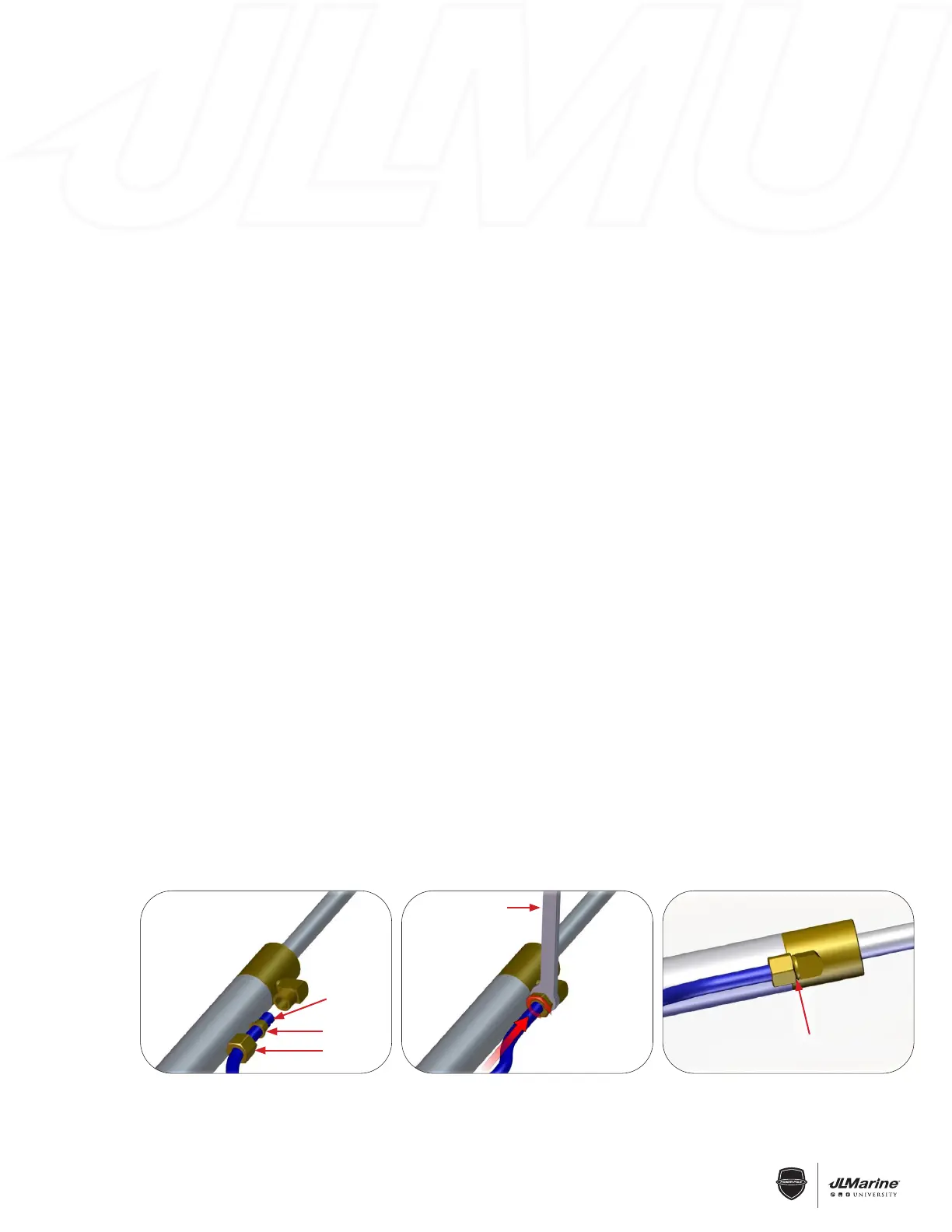
B. Disassemble both of the compression fittings by removing their nuts and ferrules. With both the blue and
black hydraulic tubing in line with their respective fittings, feed each of them through a compression fitting nut as
well as a compression fitting ferrule. ((SSeeee IImmaaggee ##11))
NNUUTT MMUUSSTT CCOOVVEERR AALLLL TTHHRREEAADDSS!!
!!
Figure 3
SECTION 2.3 – Hydraulic Systems
5/16” Compression Fittings
INSTALLATION TOOLS:
• 9/16” Wrench
• Razor Blade Knife
ROUTING:
IMPORTANT: The Hydraulic Tubing will need to be routed through the Rubber Grommet in the Upper
U-Channel and attached to the Hydraulic Cylinder via the Compression Fittings prior
to installing the Cylinder.
Route the Hydraulic Tubing according to the instructions in the Owner’s Manual. If using the supplied
Thru-Hull bushings, be sure to use an 11/32” Drill Bit instead of a 5/16” Drill Bit.
INSTALLATION (CYLINDER FITTINGS):
STEP 1 With the Tubing routed to the Cylinder, pull enough slack so the BLUE Tubing reaches the
uppermost Compression Fitting (BLUE Dust Cap) and the BLACK Tubing reaches the lower
Compression Fitting (BLACK Dust Cap).
STEP 2 Disassemble both of the compression fittings by removing their Nuts and Ferrules. With both the
BLUE and BLACK hydraulic tubing in line with their respective fittings, feed each of them through a
Compression Fitting Nut as well as a Compression Fitting Ferrule. FIG 1
IMPORTANT! The tubing needs to pass through the Ferrule far enough so there is approximately a 1/2”
length of tubing exposed. FIG 1
STEP 3 Insert the BLUE Tubing into its respective compression fitting base. With the Tubing fully
inserted, begin threading on the Compression Fitting Nut. Repeat this procedure with the
BLACK Tubing.
STEP 4 Tighten both Compression Fitting Nuts with a 9/16” Wrench. FIG 2
WARNING: The Nuts must be tightened down far enough so NONE of the Compression Fittings’ threads
are visible. Otherwise, hydraulic failure may occur. FIG 3
STEP 5 Once the Hydraulic Tubing is securely fastened to the fittings, install the Cylinder in the
Anchor, and use the supplied marine wire ties to fasten the BLUE Tubing to the Cylinder via the
instructions in the Owner’s Manual.
1
55//1166”” CCoommpprreessssiioonn FFiittttiinnggss IInnssttrruuccttiioonnss
IImmppoorrttaanntt:: TThhee hhyyddrraauulliicc ttuubbiinngg wwiillll nneeeedd ttoo bbee rroouutteedd tthhrroouugghh tthhee rruubbbbeerr ggrroommmmeett iinn tthhee uuppppeerr UU--CChhaannnneell aanndd
aattttaacchheedd ttoo tthhee hhyyddrraauulliicc ccyylliinnddeerr vviiaa tthhee ccoommpprreessssiioonn ffiittttiinnggss pprriioorr ttoo iinnssttaalllliinngg tthhee ccyy
lliinnddeerr..
Route the hydraulic tubing according to the instructions in the “Owner’s Manual”. If using the supplied thru-hull
bushings, be sure to use an 11/32” drill bit instead of a 5/16” bit.
SStteepp 11:: HHyyddrraauulliicc ccyylliinnddeerr ffiittttiinnggss
A. With the tubing routed to the cylinder, pull enough slack such that the blue tubing reaches the uppermost
compression fitting (blue dust cap) and the black tubing reaches the lower compression fitting (black dust cap).
B. Disassemble both of the compression fittings by removing their nuts and ferrules. With both the blue and
black hydraulic tubing in line with their respective fittings, feed each of them through a compression fitting nut as
well as a compression fitting ferrule. ((SSeeee IImmaaggee ##11))
NNUUTT MMUUSSTT CCOOVVEERR AALLLL TTHHRREEAADDSS!!
!!
Figure 2
9/16” Wrench
1
55//1166”” CCoommpprreessssiioonn FFiittttiinnggss IInnssttrruuccttiioonnss
IImmppoorrttaanntt:: TThhee hhyyddrraauulliicc ttuubbiinngg wwiillll nneeeedd ttoo bbee rroouutteedd tthhrroouugghh tthhee rruubbbbeerr ggrroommmmeett iinn tthhee uuppppeerr UU--CChhaannnneell aanndd
aattttaacchheedd ttoo tthhee hhyyddrraauulliicc ccyylliinnddeerr vviiaa tthhee ccoommpprreessssiioonn ffiittttiinnggss pprriioorr ttoo iinnssttaalllliinngg tthhee ccyy
lliinnddeerr..
Route the hydraulic tubing according to the instructions in the “Owner’s Manual”. If using the supplied thru-hull
bushings, be sure to use an 11/32” drill bit instead of a 5/16” bit.
SStteepp 11:: HHyyddrraauulliicc ccyylliinnddeerr ffiittttiinnggss
A. With the tubing routed to the cylinder, pull enough slack such that the blue tubing reaches the uppermost
compression fitting (blue dust cap) and the black tubing reaches the lower compression fitting (black dust cap).
B. Disassemble both of the compression fittings by removing their nuts and ferrules. With both the blue and
black hydraulic tubing in line with their respective fittings, feed each of them through a compression fitting nut as
well as a compression fitting ferrule. ((SSeeee IImmaaggee ##11))
NNUUTT MMUUSSTT CCOOVVEERR AALLLL TTHHRREEAADDSS!!
!!
Figure 1
1/2”
Ferrule
Nut
Nut Must Cover all Threads
 Loading...