MOVE ZR Installation & Owner’s Guide | 21
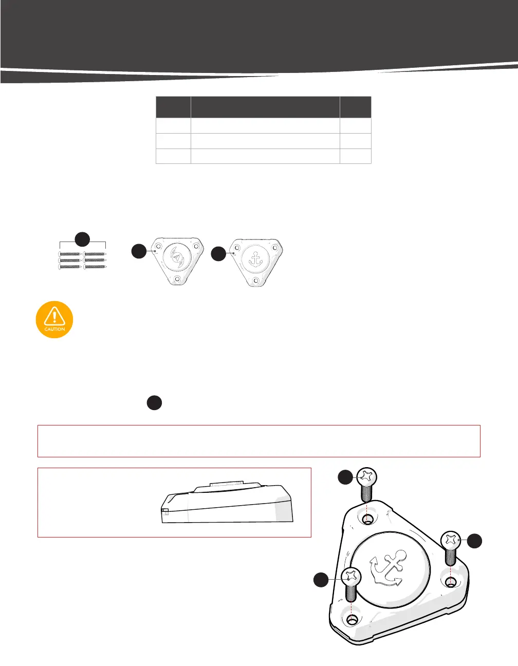
INSTALLING THE FOOT BUTTONS
LABEL DESCRIPTION QT Y.
20
#8 x 1 1/4" Pan Head Sheet Metal Screw 6
21
Active Heading Mode Foot Button 1
22
Anchor Mode Foot Button 1
STEP 1 Choose a flat surface with adequate space to mount the Foot Buttons.
STEP 2 Using the supplied template, mark mounting holes.
STEP 3 Drill mounting holes using a 7/64” drill bit.
STEP 4 Install (3) Screws
20
and tighten snug using a #2 Phillips Screwdriver.
TOOLS:
• Fine-tip Marker
• Electric Drill
• 7/64” Drill Bit
• #2 Phillips Screwdriver
FOOT BUTTON HARDWARE
IMPORTANT! If installing to gel-coat, follow the drilling procedure in Appendix A (p. 41) to ensure you do not crack
or chip the gel-coat.
NOTICE:
Tapered Side
(Toward User)
Check the area beneath where the Foot Button will be mounted to ensure there are no hoses, wires, lines, tanks,
or other sensitive components.
20
21
22
20
20
20
 Loading...