MOVE ZR Installation & Owner’s Guide | 19
INSTALLING THE REMOTE CHARGING DOCK
TOOLS:
• Fine-tip Marker
• Electric Drill
• 7/32” Drill Bit
• 7/64” Drill Bit
• #2 Phillips-Head Bit
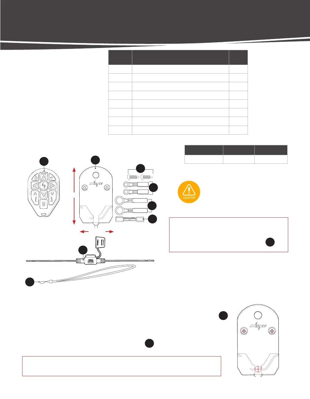
LABEL DESCRIPTION QTY.
23 Move Remote 1
24 Charging Dock 1
25 #8 x 1/2" Panhead Sheet Metal Screw 2
26 Lanyard 1
16 Heat Shrink Ring Terminal, 18-22 AWG, #10 2
17 Heat Shrink Ring Terminal, 18-22 AWG, 3/8" 2
18 Heat Shrink Butt Connector, 18-22 AWG 1
19 Fuse Holder, ATC and ATO 18 AWG, Red Leads 1
REMOTE HARDWARE
Dimensions Wire Length Wire Gauge
2 3/8" x 4 1/4" ~4 ft. 20 AWG
4 1/4"
2 3/8"
NOTICE: The Power wire can be installed through
the boat deck or directly out of the
bottom of the Charging Dock
25
.
Check the area beneath where the
Charging Dock will be mounted to
ensure there are no hoses, wires, lines,
tanks, or other sensitive components.
DRILL MOUNTING HOLES
STEP 1 Choose a flat surface with adequate space to mount the Charging Dock
24
.
STEP 2 If installing wire through boat (Preferred Method): Lay mounting template in
place, mark and drill routing hole for power wire using a 7/32" Drill Bit.
STEP 3 Mark and Drill mounting holes for Screws
25
using a 7/64” Drill Bit.
IMPORTANT! If installing to gel-coat, follow the drilling procedure in Appendix A
(p. 41) to ensure you do not crack or chip the gel-coat.
23
24
25
16
17
18
19
26
 Loading...