Q150T Sample Preparation System
10473 - Issue 5 36 Q150T - Instruction Manual
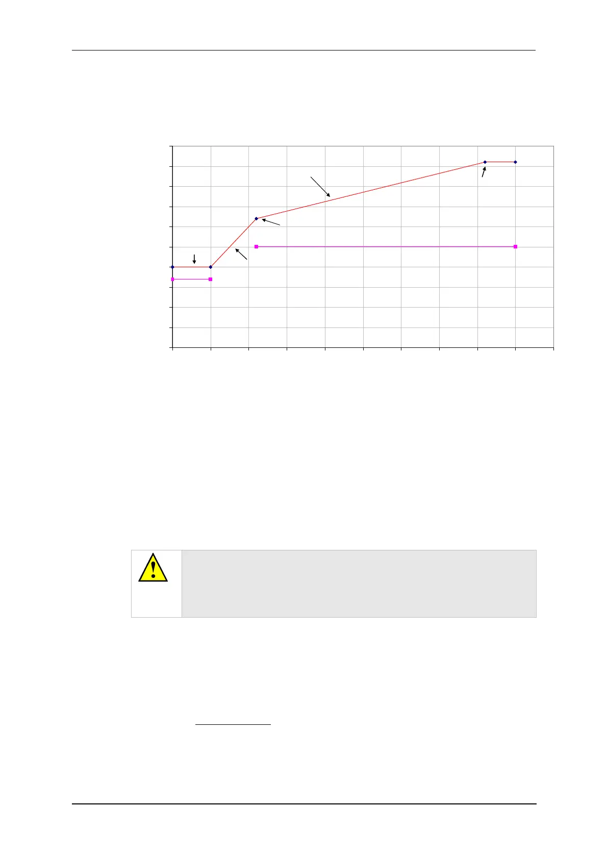
5.7.2 The ramped current profile
To achieve the controlled thickness this process uses a controlled evaporation current
profile (see Figure 5-5).
Evaporation time
Outgas time
0
5
10
15
20
25
30
35
40
45
50
0 10 20 30 40 50 60 70 80 90 100
Time(s)
Current(A)
Ramp terminated
Ramp terminated at
Evaporation Current
Current increasing at
Current increasing at
Pre Evap Rate
Outgas
Figure 5-5. Ramped Profile with default parameters
This consists of four phases:
1. The rods are outgassed at the Outgas Current for the Outgas Time. The shutter
opens and the evaporation starts.
2. The evaporation current increases at the Pre Evap Rate until the value of PreEvap
End Current is reached.
3. The evaporation current now increases at the Current Ramp Rate until the
Evaporation Current value is reached or the Evaporation Time has expired.
4. The evaporation current is held constant until the Evaporation Time has expired.
If you observe excessive sparking during the first 30 seconds of the
evaporation stage the Pre Evap End Current parameter should be reduced
by 1A at a time (but no lower than 27A).
If excessive sparking is seen 30 seconds or more into the evaporation
stage, reduce the Current Ramp Rate.
If you change Ramped Profile parameters ensure that the evaporation time is sufficient
to achieve a constant current for at least 8 seconds (but no more than 30s) at the end of
the profile.
The default settings are correct for use with a 1.4mm spigot. However, there is often a
slight variation in the tooling of the rod shapers. You can correct the default current
setting for the actual rod spigot size using the following formula:
New current =Spigot diameter
2
x Default current
1.69
For example, if the actual spigot diameter is 1.1mm you should use an evaporation
current of 30.8A.
 Loading...