Home
Radwin
Microphone system
2000
Radwin 2000 User Manual
4
of 1
of 1 rating
509 pages
Give review
Manual
Specs
To Next Page
To Next Page
To Previous Page
To Previous Page
Loading...
RADWIN
2000
Us
e
r
Manual
Rele
ase
2.8.30
2
7
‐
7
Running
the
Link
Budget
Cal
culator
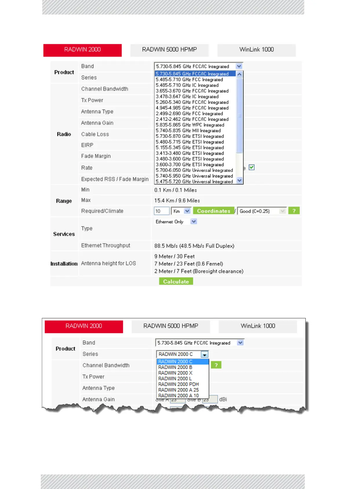
Fig
ur
e
27
‐
4:
Band
selector
2.
Chose
the
re
le
vant
RADWIN
2000
series.
Figure
27
‐
5:
RADWIN
2000
serie
s
selector
3.
Choose
the
Channel
Bandwidth.
373
375
Table of Contents
Default Chapter
4
RADWIN Worldwide Offices
4
Regulatory Compliance
5
Table of Contents
10
Part 1: Basic Installation
24
Chapter 1: About this User Manual
25
Manual Structure
25
Table 1-1 User Manual - G
25
Terminology
26
Chapter 2: Introduction
28
Welcome to RADWIN 2000
28
What's New in Release 2.8.30
28
Supported Frequencies Summary
30
Table 2-2 Frequencies for
30
Key Features of RADWIN 2000
32
Components of a RADWIN 2000 Link
35
Chapter 3: Site Survey
37
Planning the Link Site
37
The Site Survey
37
Stage 1: Preliminary Survey
38
Stage 2: Physical Survey
39
Stage 3: RF Survey
40
RF Planning for Dense Installations and Collocated Sites
40
Chapter 4: Hardware Installation
42
What's in the Box
43
Only
44
Ports
45
Plug
46
Single
47
Single
48
Single
49
Single
50
Protectors
51
Tools Required for Installation
52
Repeater
52
Safety Practices
53
Before Field Installing Odus
54
Hardware Installation Workflow for a RADWIN 2000 Link
55
Table 4-1 Bill of Materials : S
56
Pole
56
Mounting
57
Adapter
58
Adapter
59
Adapter
60
Adapter
62
Ports
63
Table 4-4 Components of an
64
Adapter
67
Adapter
68
Figure 4-47 Exposing the Tack
73
Figure 4-48 Start and End
74
Figure 4-49 Protecting the Figure 4-50 Mounted and
74
Figure 4-51 Sing an Ethernet
76
Connecting and Aligning Odus / Antennas
77
Figure 4-52 Beep Sequence
78
Installing the RADWIN Manager Application
79
Getting Started with the RADWIN Manager
79
Figure 5-2 Pinging an Figure 5-3 First Time Log - on
81
The RADWIN Manager Log-On Concept
82
Figure 5-4 Extended Log - on
82
Figure 5-5 Log on Window
83
Table 5-2 User Types , Default
83
Log-On Errors and Cautions
85
Figure 5-6 Unsupported Device
85
Figure 5-7 Unreachable Device
85
Figure 5-8 Invalid Password
86
Figure 5-9 Logging on to an Figure 5-10 Opening Radwin M
87
Table 5-3 Default Andi
88
First Steps
89
Using RADWIN Manager Spectrum View
90
Figure 5-11 Spectrum View - O
91
Chapter 6: Installing the Link
92
Overview
92
Table 6-1 Link Installationw
93
Installation
94
Figure 6-1 Link Installationw
94
Figure 6-2 Installation Wizard
95
Figure 6-3 Installation Wizard
96
Figure 6-4 Change Linkp
97
Figure 6-5 Lost or Forgotten
97
Figure 6-6 Channel Settings
98
Figure 6-7 Choosing Preferred
99
Figure 6-8 Channel Settings
99
Figure 6-9 Channel Settings
100
Figure 6-10 Transmissionp
101
Figure 6-12 Antenna Type
103
Figure 6-13 Antenna Parameters
104
Figure 6-14 T Xpower Limits
104
Figure 6-15 Antennas
105
Figure 6-17 Services and Rates
107
Figure 6-18 Services and Rates
108
Figure 6-19 Services and Rates
110
Figure 6-21 Tdm Service Port
111
Figure 6-23 Services and Rates
113
Figure 6-24 Services and Rates
114
Figure 6-25 Choosing Hots
115
Figure 6-28 Services and Tdm
117
Figure 6-34 Installationw
122
Figure 6-35 Main Window of
123
Figure 6-36 Installation with
124
Figure 6-37 Installation with
125
Figure 6-38 Using G B E Idu-C
126
Chapter 7: The RADWIN Manager: Main Window
127
The Main Window of the RADWIN Manager
127
Figure 7-1 Main Window , W
127
The RADWIN Manager Tool Bar
128
Main Menu Functionality
128
Table 9-1 Site
130
Table 9-2 Site
130
Elements of the RADWIN Manager Main Window
131
Table 7-3 Status Bar Indicators
135
Chapter 8: Configuring the Link
136
Overview
136
Table 8-1 Link Configuration
137
Configuration
138
Figure 8-1 Link Configuration
138
Figure 8-2 Configurationw
139
Figure 8-3 Channel Settings
140
Figure 8-4 Searching for the Figure 8-5 Channel Settings
141
Figure 8-6 Channel Frequency
143
Figure 8-7 Choosing an "O
144
Figure 8-8 Transmission Power
145
Figure 8-9 Antenna Configuration
146
Figure 8-11 Services and Rates
149
Figure 8-13 Configurationw
151
Figure 8-14 Main Window of
152
Chapter 9: Site Configuration
153
Configuring the Site
153
Figure 9-1 Configurationd
154
Viewing System Details
155
Viewing Air Interface Details
156
Changing the Transmit Power
156
Figure 9-2 Changing Thea
157
Hub Site Sync
158
IP Address, VLAN and Protocol
159
Figure 9-4 Managementa
160
Figure 9-5 Configuring
162
Figure 9-6 Supported Protocols
163
Displaying the Inventory
164
Security Features
165
Figure 9-7 Inventory Window
165
Figure 9-8 Available Security
166
Figure 9-9 Changing Thec
168
Figure 9-10 Alternativec
169
Setting the Date and Time
171
Figure 9-11 Date and Timec
173
Figure 9-12 Change Date and Figure 9-13 Date and Time
174
Ethernet Properties
175
Figure 9-14 Bridge , Vlan and Figure 9-15 Bridge , Vlan and
176
Figure 9-19 Ethernetc
188
Figure 9-20 Ethernet mir - T
189
Figure 9-21 Air Interface
189
TDM MHS Status
190
Setting External Alarm Inputs
191
Resetting
192
Figure 9-23 External Alarms
192
Figure 9-24 Site Configuration
193
IDU Detection
194
Backup/Restore of ODU Software Files
194
Muting the Alignment Tone Buzzer
196
Configuration with Telnet
196
Figure 9-25 Alignment Tone
196
Figure 9-26 Telnet Session Log
197
Table 9-4 Telnet - Display
197
Table 9-5 Telnet - Set Immediate
198
Table 9-6 Telnet - Set Commands
199
Chapter 10: Monitoring and Diagnostics
201
Retrieving Link Information (Get Diagnostics)
201
Figure 10-1 Get Diagnostics
202
Table 10-1 Get Diagnosticsd
202
Link Compatibility
203
Table 10-2 Link Compatibility
203
TDM Loopbacks
204
Figure 10-2 Loopback
204
Figure 10-3 Loopback
204
Figure 10-4 Loopback Options
205
Figure 10-5 Loopback Defined
205
Figure 10-6 Site Aport 2 Set
206
Figure 10-7 Local Line Loopback
207
Figure 10-8 Remote Reverse
207
Figure 10-9 Remote Linel
208
Figure 10-10 Local Reversel
208
Reinstalling and Realigning a Link
209
The Link Budget Calculator
209
Throughput Checking
209
Performance Monitoring
210
Figure 10-11 Preferences
211
Figure 10-12 Basic Performance
212
Figure 10-13 Typicalp
212
Figure 10-14 Performancem
213
Table 10-3 Explanation of
213
Figure 10-15 Threshold
215
Table 10-4 Action of the
215
Events, Alarms and Traps
216
Figure 10-16 Events Logd
217
Figure 10-17 Preferences
220
Figure 10-18 Active Alarmss
221
Table 10-6 Active Alarms
221
Reverting Alert Messages
222
Figure 10-19 Recent Events - U
222
Other Advanced Preferences
223
Remote Power Fail Indication
223
Figure 10-20 Advancedp
223
Troubleshooting
224
Table 10-7 Led Fault Indicators
224
Table 10-8 Systemt
224
Replacing an ODU
225
Restoring Factory Setup
225
Online Help
225
Customer Support
226
Part 2: Site Synchronization
227
Chapter 11: Hub Site Synchronization
228
What Is Hub Site Synchronization (HSS)
228
Radwin Hss
228
Figure 11-1 Interference
229
Figure 11-2 Collocated Units
229
Figure 11-3 Collocated Units
229
HSS Concepts: Radio Frame Pattern (RFP)
231
Figure 11-4 Radio Framep
231
Table 11-1 Radio Framep
231
Table 11-2 Radio Framep
231
Table 11-3 Legend for Radio
232
HSS Status LED on the IDU-C and IDU-E
234
Table 11-4 Asymmetrica
234
HSS Error Notification
235
Figure 11-7 Odu Beep for
235
Chapter 12: Serial Hub Site Synchronization
236
RADWIN Serial HSS
236
Hardware Installation
236
Figure 12-3 Hss Sync Signal
238
Figure 12-4 Cascading Two
239
Figure 12-5 Cascading Three
239
ODU/HSS Unit Connection Pinout
240
Link Configuration and HSS
241
Table 12-1 External Pulses
242
Figure 12-7 Hub Sitec
243
Site Configuration and SHSS
244
Figure 12-8 Site Configuration
244
Chapter 13: Hub Site Synchronization over Ethernet
245
RADWIN Ethernet HSS
245
Installing Collocated Hssoe Odus
246
Link Configuration and Hssoe
247
Table 13-1 Link Settings to
247
Site Configuration and Hssoe
254
Mixing Hssoe and SHSS Enabled Odus
255
Figure 13-4 Site Configuration
255
Chapter 14: Using the RADWIN GSU
256
What Is It for
256
GSU Functionality
256
Typical GSU Scenarios
256
GSU Redundancy
258
Figure 14-3 Phase Shifted
258
GSU Kit Contents
259
Figure 14-4 Make the Gsus
259
GSU Installation
260
Figure 14-5 General Gsu
260
Figure 14-7 Site Configuration
262
Figure 14-8 Site Configuration
263
Figure 14-9 Site Configuration
265
Figure 14-10 Site Configuration
266
Figure 14-11 Site Configuration
267
Figure 14-12 Setting the Date
268
Figure 14-13 Site Configuration
269
GSU Monitoring and Diagnostics
270
GSU Telnet Support
270
Figure 14-14 Site Configuration
270
Software Upgrade for Gsus
271
Part 3: Advanced Installation
272
Chapter 15: Monitored Hot Standby Installation Procedure
273
What Is a RADWIN Monitored Hot Standby
273
What RADWIN MHS Provides
274
Purpose of this Chapter
275
Who Should Read this
275
RADWIN MHS Kit Contents
275
Installing a RADWIN MHS
275
Figure 15-3 How to Connect
276
Figure 15-4 Servicesc
277
Figure 15-5 the Primary Link
278
Figure 15-6 the Secondary
279
Figure 15-7 Primary Linka
280
Maintaining a RADWIN MHS Link
281
Figure 15-8 Secondary Link
281
Switching Logic
283
Figure 15-9 Primary Link after
283
Figure 15-10 Secondary Link
284
Figure 15-11 Primary Link
285
Figure 15-12 Secondary Link
286
Chapter 16: The RADWIN Ethernet Ring
287
Scope
287
What Is an Ethernet Ring
287
RADWIN Ethernet Ring
288
Figure 16-1 Ring Protection
288
Ethernet Ring Topologies Supported by RADWIN
290
Table 16-1 Topologies
290
Protection Switching
292
Hardware Considerations
292
Special Case: 1 + 1 Ethernet Redundancy
293
Figure 16-2 Node with Idu
293
Figure 16-3 1+1 Ethernet
293
Using RADWIN Manager to Set up a Ring
294
Figure 16-4 Using Idu-Cor
294
Figure 16-5 Services Window
294
Figure 16-6 Ring Options
295
Figure 16-7 Configuring Ring
295
Figure 16-8 Configuring Rpl VID
296
Chapter 17: VLAN Functionality with RADWIN 2000
299
VLAN Tagging - Overview
299
Figure 17-1 Two Network
300
Figure 17-2 Separating Client
300
Table 17-1 Port Settings - I
302
Table 17-2 Port Settings - E
302
VLAN Availability
304
VLAN Configuration Using the RADWIN Manager
305
Figure 17-7 Untagging Selected
308
Figure 17-8 Provider Parameters
308
Chapter 18: Software Upgrade
309
What Is the Software Upgrade Utility
309
Upgrading an Installed Link
309
Figure 18-1 Software Upgrade
310
Figure 18-2 Add Site Options
310
Figure 18-3 Adding Asingle
311
Figure 18-4 Software Upgrade
312
Software Upgrade for Gsus
313
Figure 18-5 Software Upgrade
313
Figure 18-6 Software Upgrade
313
Chapter 19: False Radar Mitigation Facilities
314
Who Needs It
314
DFS and False Radar Mitigation
314
FCC/IC 5.4/5.3 Ghz Links: Background
315
Figure 19-1 Channel Select
316
Configuring False Radar Mitigation
318
Figure 19-2 False Radarm
318
FCC/IC Requirements
319
Chapter 20: FCC/IC DFS Considerations
320
FCC 5.4Ghz Device Registration
320
Registering the Device
320
TDWR Table
324
Figure 6-11 Antenna
324
Table 20-1 Latitude and Table 21-1 Default Priorities
324
Chapter 21: Quality of Service
326
Availability
326
Qos - Overview
326
Setting up Qos
327
Figure 21-1 Services Window
327
Figure 21-2 Ethernet Q O S C
328
Figure 21-3 Top : Vlan
329
Disabling Qos
330
Figure 21-4 mir Choice - Per
330
Chapter 22: Capacity Upgrade
331
What Is Capacity Upgrade
331
Applicability
331
Data Gathering
331
Acquisition
332
Application
332
Chapter 23: Changing the Factory Default Band
335
Why this Is Needed
335
Required Equipment
335
The Procedure
335
Figure 23-1 Becoming Installer
336
Figure 23-2 Opening Manager
337
Figure 23-3 Change Band
337
Figure 23-4 Adifferent Band
338
Figure 23-5 Change Band
338
Changing Band for DFS
339
Special Products or Features: Entering a License Key
339
Figure 23-6 Main
339
Figure 23-7 Using Theo
340
Provisions for Licensed 3.X and 2.5 Ghz Bands
341
Chapter 24: Quick Install Mode
350
Why this Is Needed
350
Enabling Quick Install
350
Using Quick Install
351
Figure 24-1 Preferences : Q
351
Figure 24-2 New Install Mode
351
Figure 24-3 Change Toi
352
Figure 24-4 Service Mode
352
Figure 24-5 Resumption of
352
Chapter 25: BRS/EBS Considerations
354
What Is BRS/EBS
354
BRS/EBS Bands
354
Setting up a BRS/EBS Link Using RADWIN 2000 2.5Ghz Band
358
Part 4: Field Installation Topics
359
Chapter 26: Pre-Loading an ODU with an IP Address
360
Why this Is Needed
360
Required Equipment
360
The Procedure
361
Figure 26-1 Log on Window
361
Figure 26-2 Opening Radwin M
362
Figure 26-3 Configurationd
363
Figure 26-4 Managementa
364
Figure 26-5 Odu with Ip a
365
Figure 26-6 Confirmation of
365
Figure 26-7 Main Window
366
Tip: How to Recover a Forgotten ODU IP Address
367
Figure 26-8 Existing Ip Address
367
Chapter 27: Link Budget Calculator
368
Overview
368
Calculations
369
About the Fresnel Zone
370
Figure 27-1 Fresnel Zone
371
Running the Link Budget Calculator
372
Figure 27-2 Accessing Thel
372
Figure 27-3 Link Budget
373
Figure 27-4 Band Selector
374
Figure 27-5 Radwin 2000
374
Figure 27-9 Rate Selector
376
Figure 27-10 Calculation of
377
Figure 27-11 Climacticc F
378
Figure 27-12 Climacticc F
378
Figure 27-13 World Map
379
Chapter 28: Spectrum View
381
What Is Spectrum View
381
Running Spectrum View
381
Figure 28-1 Starting the Figure 28-2 Sitea ( Managing
382
Figure 28-3 Siteb
384
Understanding the Spectrum View Display
385
Figure 28-5 Selecting an Area
386
Figure 28-6 Requested Section
387
Figure 28-7 Spectrum Views
387
Figure 28-8 Effect of Setting
388
Figure 28-9 Effect of Setting
388
Figure 28-10 Further Viewing
389
Figure 28-11 Antennaa
389
Chapter 29: Using the Web Interface
392
What Is It for
392
Who Needs It
392
How It Works
392
What It Provides
393
Prerequisites
393
Special Considerations Working with the WI
393
Figure 29-1 Web Interface - a
394
Scope of this Chapter
395
Logging on
395
Figure 29-2 Web Interface - L
395
Figure 29-3 Web Interface - M
396
Figure 29-4 Web Interface - M
396
Using the Configuration Wizard
397
Figure 29-5 Web Interface - C
397
Figure 29-6 Web Interface - C
398
Figure 29-7 Web Interface - I
398
Figure 29-8 Web Interface - a
400
Figure 29-9 Web Interface - C
401
Site Configuration
404
Figure 29-10 Web Interface - C
404
Figure 29-11 Web Interface
404
Figure 29-12 Web Interface
405
Figure 29-13 Web Interface
405
Figure 29-14 Web Interface
406
Figure 29-15 Web Interface
407
Figure 29-16 Web Interface
408
Figure 29-17 Web Interface
409
Figure 29-18 Web Interface
410
Figure 29-19 Web Interface
411
Figure 29-20 Web Interface
411
Figure 29-21 Web Interface
411
Figure 29-22 Monitor Panel
412
Part 5: Product Reference
413
Scope of These Specifications
414
Odu
414
Idu-E
420
Idu-C
422
IDU-H (Aggregation Unit
424
Gbe Poe Device - Indoor, AC
425
Poe Device - Outdoor, DC
426
Gsu
427
Lightning Protector
428
Fast Ethernet CAT-5E Cable Repeater
429
Antenna Characteristics
430
Appendix B: Wiring Specifications
431
ODU-IDU Cable
431
ODU/HSS Unit Connection Pinout
431
User Port Connectors
432
Figure 9-16 G B E Lan Port
432
Figure B-1 Example for Figure B-2 Unbalanced E1
434
DC Power Terminals
435
Unbalanced Mode for E1 Interface
435
Figure B-3 Unbalanced E1
436
Appendix C: Small Form-Factor Pluggable Transceiver
437
IDU-C SFP Support
437
Appendix D: MIB Reference
438
Introduction
438
Interface API
439
Private MIB Structure
439
Figure D-1 Top Level Sections
440
Figure D-2 Product Mib for Figure H-1 Grande Clame
440
MIB Parameters
441
Appendix E: External Alarms Specification
488
External Alarms Specification
488
Appendix F: Setting Antenna Parameters
490
Antenna Issues
490
About Single and Dual Antennas
490
Considerations for Changing Antenna Parameters
493
Appendix G: RF Exposure
495
Appendix H: Regional Notice: French Canadian
496
Procédures de Sécurité
496
Installation Sur Pylône Et Mur
498
Figure H-3 Bras
498
Figure H-5 Montage Sur un
500
Index
502
4
Based on 1 rating
Ask a question
Give review
Questions and Answers:
Need help?
Do you have a question about the Radwin 2000 and is the answer not in the manual?
Ask a question
Radwin 2000 Specifications
General
Brand
Radwin
Model
2000
Category
Microphone system
Language
English
Related product manuals
Radwin 2000 Series
446 pages
Radwin 2000 D+
229 pages
Radwin 2000 C PLUS
297 pages
Radwin 2000+ SERIES
276 pages
Radwin 2000 Alpha INT
6 pages
Radwin RW 2000 Series
127 pages
Radwin 1000
211 pages