Rockwell Automation Publication 2198-RM006A-EN-P - December 2020 49
Appendix A Connectors and Field Connections
Kinetix 5300 Servo Drive Connector Data
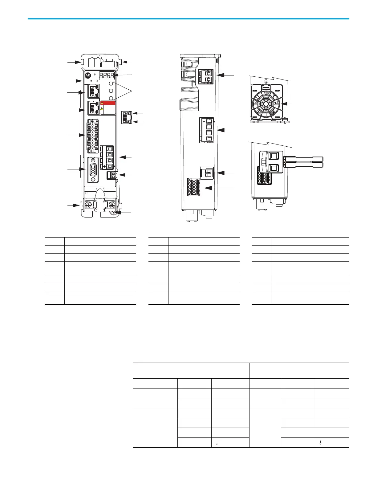
Figure 19 - Drive Features and Indicators
Input and Motor Power
Connector Pinouts
These tables compare the input power, control/auxiliary power, motor power,
and shunt resistor connector pinouts for the Ultra3000 and Kinetix 5300 servo
drives.
18
17
16
15
L3
L2
L1
1
8
2
3
11
4
5
9
10
14
6
7
13
12
L3L2
L1
24+
DC+ SH
24-
SB+
SB-
S1
SC
S2
7
SB+
SB-
S1
SC
S2
2
1
2
1
MOD NET
MBRK
W
V
U
1
10
1
2
MFB
SELECT
BACK
NEXT
KINETIX
5300
DANGER
Electric shock
risk. Power
o and wait
5 minutes.
U
V
W
Kinetix 5300 Drive, Front View
(2198-C1004-ERS drive is shown)
Kinetix 5300, Top View
(2198-C1004-ERS drive is shown)
Shared-bus 24V Input
Wiring Connector
Kinetix 5300, Bottom View
(frame 2 and 3 drives only)
Cooling Fan
Item Description Item Description Item Description
1 Motor Cable Shield Clamp 7 Zero-stack Mounting Tab/Cutout 13 Motor Brake Connector
2 Motor Feedback (MFB) Connector 8 Four-character Status Display 14 Ground Terminal
3
Digital Inputs and Auxiliary Feedback
Connector
9 Navigation Pushbuttons 15 Shunt Resistor Connector
4 Ethernet (PORT1) RJ45 Connector 10 Link Speed Status Indicators 16 AC Mains Input Power Connector
5 Ethernet (PORT2) RJ45 Connector 11 Link/Activity Status Indicators 17 24V Control Input Power Connector
6
Module and Network Status
Indicators
12 Motor Power Connector 18 Safe Torque Off (STO) Connector
Table 36 - Single-phase Connectors
Ultra3000 Servo Drives
(Cat. No. 2098-DSD-005, -010, -20, and -030)
Kinetix 5300 Servo Drives
Connector Signal Terminal Connector Signal Terminal
DC Bus Connections
DC+ +
—
——
DC- – — —
Single-phase Input
Power
L1 L1
Single-phase
Input Power
L1 L1
L2/N L2/N L2/N L2
—— ——
Ground Ground

 Loading...


