22 Rockwell Automation Publication 6300P-UM001B-EN-P - March 2021
Chapter 3 Operate the Panel PC
Touch Screen Calibration
VersaView 6300P panel PCs with analog resistive touch screens use an eGalax
driver and can be field calibrated. VersaView 6300P panel PCs with PCAP
touch screens use the native Microsoft Windows Human Interface Device
(HID) driver and cannot be field calibrated.
Start the Panel PC
Follow these steps to start your VersaView 6300P panel PC.
1. Make sure that all necessary peripheral devices are connected to the
corresponding I/O ports on the panel PC.
2. Make sure any connected components with separate power supplies
(such as an external display) are turned on first.
3. To power on the computer, turn on the main DC power switch or
breaker.
Light-emitting Diode and
Button Descriptions
After a VersaView 6300P panel PC is powered on, various light-emitting diodes
(LEDs) monitor its state. Use these LEDs to determine if they are lit and what
color they emit. There are also buttons on the computer to reset computer
states that are monitored by the LEDs.
The following tables detail what LEDs and buttons are on a panel PC.
IMPORTANT The following steps apply to when the panel PC must be started manually,
and power has been connected already.
See Connect DC Power
on page 19 for when power is applied to the panel PC for
the first time.
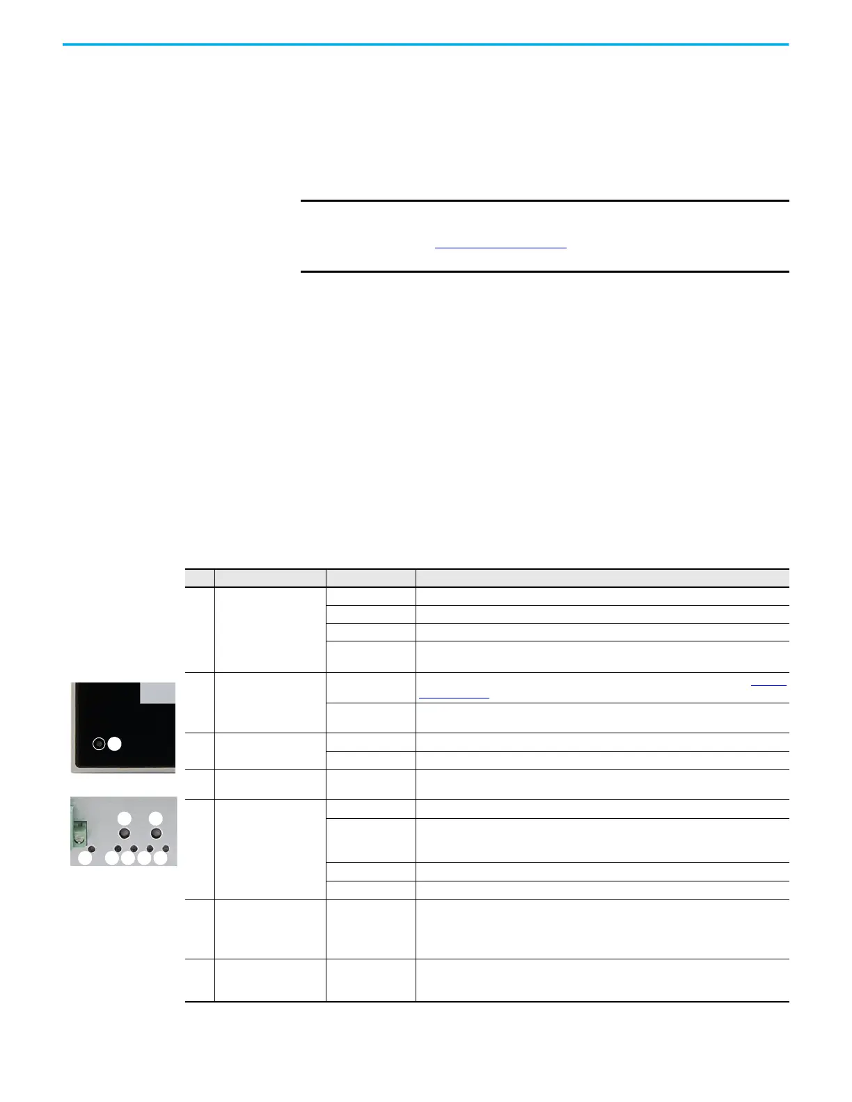
Table 2 - LEDs and Buttons
No. Description Color Function
1 Power supply LED
No color The computer is not powered.
Green The computer is on and powered by the main power supply.
Flashing green The computer is on and powered by an uninterruptible power supply (UPS).
Yellow
If a UPS is connected, verify that the UPS connection is secure or that the UPS battery is not
faulty.
2
Over temperature/
battery fault LED
Red
The computer has exceeded its operating temperature. For more information, see Thermal
Alarm on page 39.
Flashing red
The real-time clock (RTC) battery is lower than 2.5V. Replace before the battery goes lower
and risks loss of date and time.
3Watchdog LED
Green The watchdog is working.
Red The watchdog timer has expired.
4Mass storage LED Yellow
When lit, access to a mass storage device (SSD or CFast) is happening through a SATA
channel.
5 On/Off/Standby/UPS LED
No color The computer is powered off or the CPU is not starting.
Green
• The computer is powered on.
• The system is in a low-power state, and current session information is being stored in
the RAM.
Flashing green The computer is powered but a UPS is powering the system while main power is missing.
Yellow The computer is safe to power off; the operating system has been shut down successfully.
6 System reset button —
Forces an internal reset, as if power was lost temporarily and then returned.
IMPORTANT: Use this button only if there are no better options, like keyboard or mouse
commands, or if the resumed DC power does not restart the computer. System reset can
cause data loss and possible corruption to the operating system.
7 Watchdog reset button — Turns off the watchdog LED (item 3).
1
Display Bezel
(1)
Computer Chassis
2 3 4 5
6 7
5
(1) Aluminum glass
True Flat bezel shown.
 Loading...