38 Publication 2711P-UM001I-EN-P - December 2008
Chapter 2 Installation
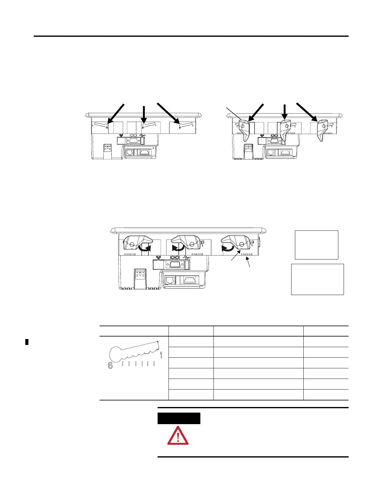
6. Insert all mounting levers into the mounting slots on the
terminal.
Slide each lever until the flat side of the lever touches the
surface of the panel.
7. When all levers are in place, slide each lever an additional notch
or two until you hear a click.
8. Rotate each lever in the direction indicated until it is in the final
latch position.
Follow the latching sequence for the optimum terminal fit.
Use this table as a guide to provide an adequate gasket seal
between the terminal and the panel.
Mounting Slots
Mounting Levers
Flat Side of Lever
Notch
61
Alignment Marks
Rotate lever until notch in
lever aligns with proper
alignment mark on terminal.
6 Levers
246
513
14
3
2
4 Levers
Lever Position Panel Thickness Range Typical Gauge
1 1.5…2.01 mm (0.060…0.079 in.) 16
2 2.03…2.64 mm (0.08…0.104 in.) 14
3 2.67…3.15 mm (0.105…0.124 in.) 12
4 3.17…3.66 mm (0.125…0.144 in.) 10
5 3.68…4.16 mm (0.145…0.164 in.) 8/9
6 4.19…4.75 mm (0.165…0.187 in.) 7
Terminal
Markings
1
2
3
4
5
6
ATTENTION
Follow instructions to provide a proper seal and to
prevent potential damage to the product. Rockwell
Automation assumes no responsibility for water or
chemical damage to the terminal or other equipment
within the enclosure because of improper installation.
 Loading...