Publication 2711P-UM001I-EN-P - December 2008 155
Install and Replace Components Chapter 6
8. Insert the new battery.
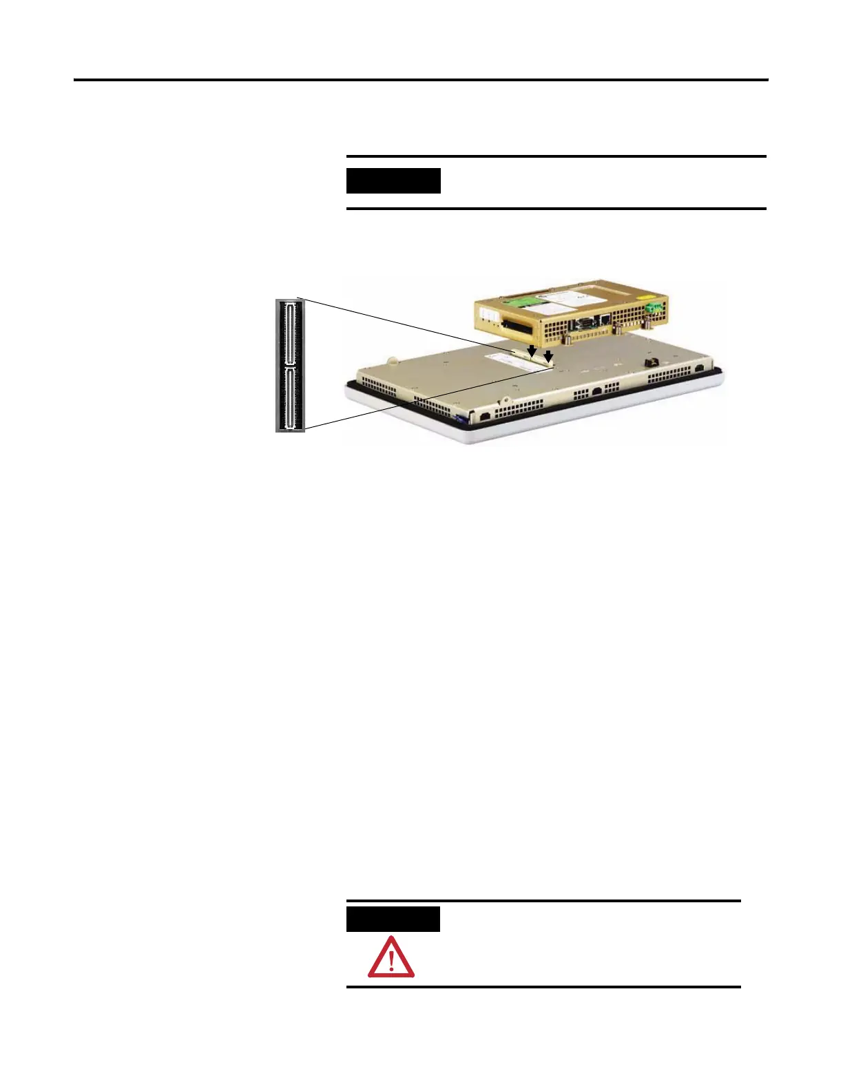
9. Attach the logic module by aligning the two connectors on the
bottom of the module with the connectors on the terminal.
10. Push down on the logic module until firmly seated.
11. Tighten the six captive screws that secure the logic module to a
torque of 0.58 Nm (5…7 lb•in).
12. Attach the communication module (if necessary) and tighten the
four screws to a torque of 0.58 Nm (5…7 lb•in).
Replace the Bezel
It is not necessary to remove the logic module or communication
module before removing the bezel, except on the PanelView Plus 700
terminal.
Remove the Display Module Bezel
Follow these steps to remove the display module bezel on a 700 to
1500 terminal.
1. Disconnect power from the terminal.
2. Set the terminal, display side down, on a flat stable surface.
IMPORTANT
Use only replacement battery 2711P-RY2032.
ATTENTION
Wear a properly grounded ESD wristband before
touching any of the electronic components in the
logic module.
 Loading...