PowerFlex Digital DC Drive User Manual - Publication 20P-UM001C-EN-P - July 2008
Programming and Parameters 3-35
APPLICATIONS
PI Control
779 [PI Central v sel]
Selects one of the four possible initial output values of the PID
regulator integral component (corresponding to the initial diameter) of
the PI block.
• “0” = When the PI block is disabled (Par 769 [Enable PI] =
“Disabled”), the last value of the integral component calculated
(corresponding to swift diameter) is stored in Par 771 [PI Output].
This value is used by the PID regulator when the PI block is
enabled again and the drive is restarted. This function is useful
when for any reason the drive must be turned off or if incoming
power is removed from the drive.
• “1”, “2”, or “3” = When the PI block is disabled (Par 769 [Enable PI]
= “Disabled”), the value of [PI Output] will be set to the value of the
selected parameter (“1” = 776 [PI Central v1], “2” = 777, [PI Central
v2], or “3” = 778 [PI Central v3] x1000). This value is only used by
the PID regulator when the drive is powered up and Par 769
[Enable PI] is already enabled.
Note: Par 779 [PI Central v sel] can be set directly from the HIM or
through two digital inputs set respectively as “PI central vs0” and “PI
central vs1”. Refer to Pars 780 [PI Central vs0] and 781 [PI Central
vs1] for more information on this configuration.
Default:
Min/Max:
1
0 / 3
769,
776,
777,
778,
780,
781
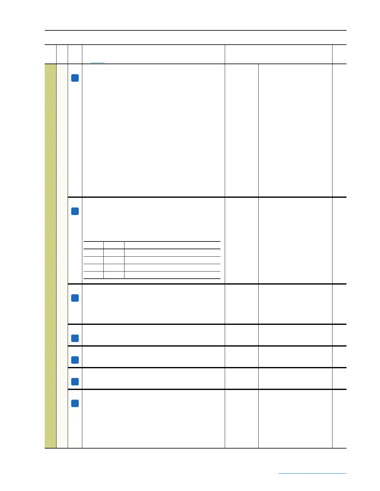
780 [PI Central vs0]
When assigned to a digital input and used in combination with Par
781 [PI Central vs1], through binary selection, determines which of
the four possible output values is used as the initial level of the
integral component (corresponding to the initial diameter) of the PI
block.
Default:
Min/Max:
0
0 / 1
781 [PI Central vs1]
The output selector of the initial PI block. With the value of Par 780 [PI
Central vs0] determined, through binary selection, what between the
four possible settings of the integral initial level (correspondent to
initial diameter) can be used. See Par 780 [PI Central vs0] for binary
selections.
Default:
Min/Max:
0
0 / 1
783 [PI integr freeze]
Locks the selections made for the integral component of the PID
regulator.
Default:
Options:
0 =
0 =
1 =
“Off”
“Off”
“On”
784 [PI Upper Limit]
Defines the upper limit of the adapting block for correction of the PI
block.
Default:
Min/Max:
10.00
Par 785 [PI Lower Limit] / 10.00
785 [PI Lower Limit]
Defines the lower limit of the adapting block for correction of the PI
block.
Default:
Min/Max:
0.00
–10.00 / Par 784 [PI Upper Limit]
793 [PI Init Prop Gn]
The initial value of the proportional gain. This parameter is active
when,
• its value has exceeded the value of Par 695 [PI Steady Thrsh],
• the amount of time defined in Par 731 [PID Steady Delay] has
elapsed, and feed–forward is less than the value defined in Par 695
[PI Steady Thrsh], or
• Par 769 [Enable PI] transitions from “0” (low) to “1” (high) and the
amount of time defined in Par 731 [PID Steady Delay] has elapsed.
Default:
Min/Max:
10.00
0.00 / 100.00
695,
731,
769
File
Group
No.
Parameter Name & Description
See page 3-2 for symbol descriptions
Values
Related
A
A
Par 780 Par 781 Selects the value in . . .
0 0 Par 771 [PI Output]
0 1 Par 776 [PI Central v1]
1 0 Par 777 [PI Central v2]
1 1 Par 778 [PI Central v3]
A
A
A
A
A
 Loading...


