PowerFlex Digital DC Drive User Manual - Publication 20P-UM001C-EN-P - July 2008
C-2 Application Notes
Example 2:
An external analog reference reaches a maximum value of 9.8V. Enter a
scaling factor of 1.020 in [Anlg Inx Scale] to scale the maximum voltage
from 9.8V to 10V.
The same result could be obtained via parameter [Anlgx Tune Scale], by
entering the values of the appropriate parameters via the HIM. The
maximum possible analog value (in this case 9.8V) would have to be
present at the terminal with a positive polarity.
Analog Input Signal Comparison
This feature provides an indication via the HIM or a digital output when the
signal of analog input 1 has reached a limit above or below a set reference
point.
Calculations used to determine Pars1042 [Anlg In1 Cmp] and 1043 [Anlg
In1 Cmp Err]:
• [Anlg In1 Cmp] = (comparison value) x 10000 / (max. reference value)
• [Anlg In1 Cmp Err] = (tolerance value) x 10000 / (max. reference value)
Example 1:
An application requires an indication via a digital output that the motor
speed is within 100 RPMs of 700 RPM.
• Par 45 [Max Ref Speed] = 1500 RPM (maximum reference value)
• For Analog Input 1, 10V or 20mA sets the maximum value of Par 44
[Speed Ref A] = Par 45 [Max Ref Speed]
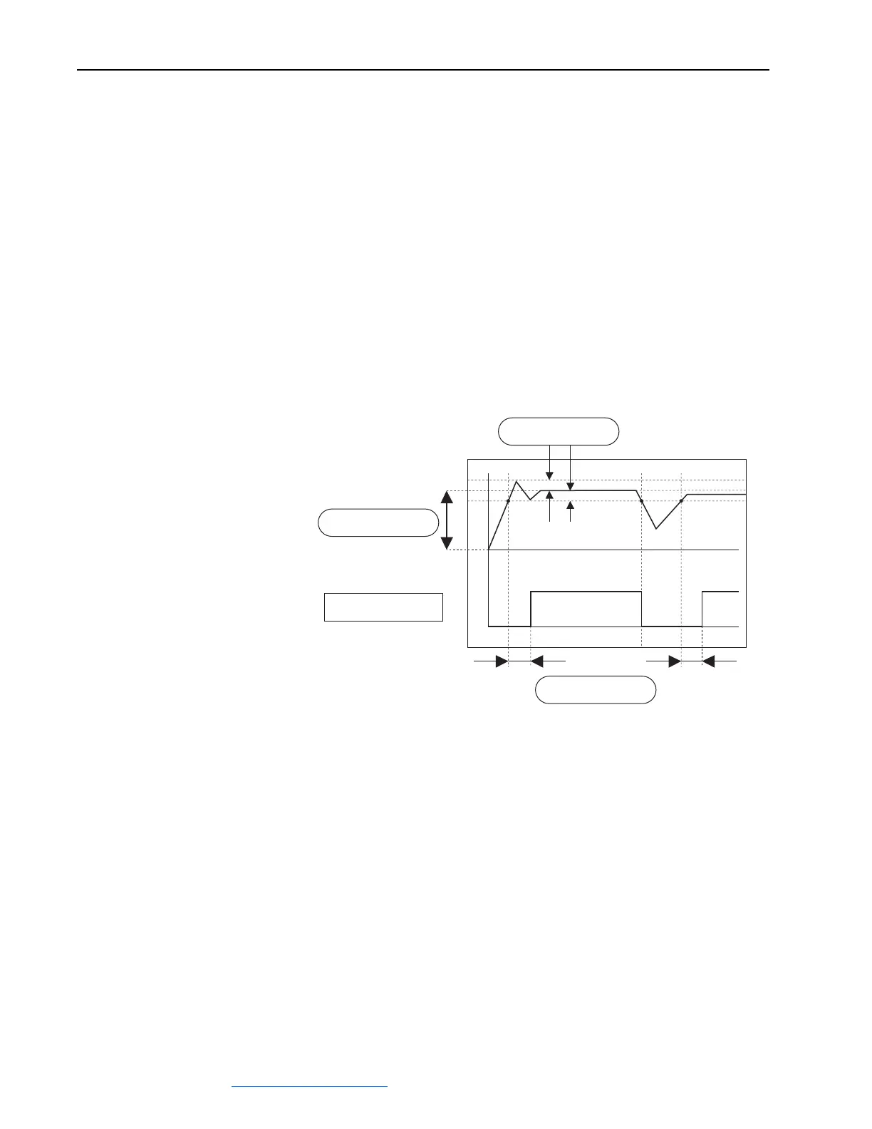
Anlg In1 Cmp
0
0 ms
Anlg In1 Cmp Eq
Anlg In1 Cmp Dly
Anlg In1 Cmp Err
0
 Loading...


