PowerFlex Digital DC Drive User Manual - Publication 20P-UM001C-EN-P - July 2008
Appendix C
Application Notes
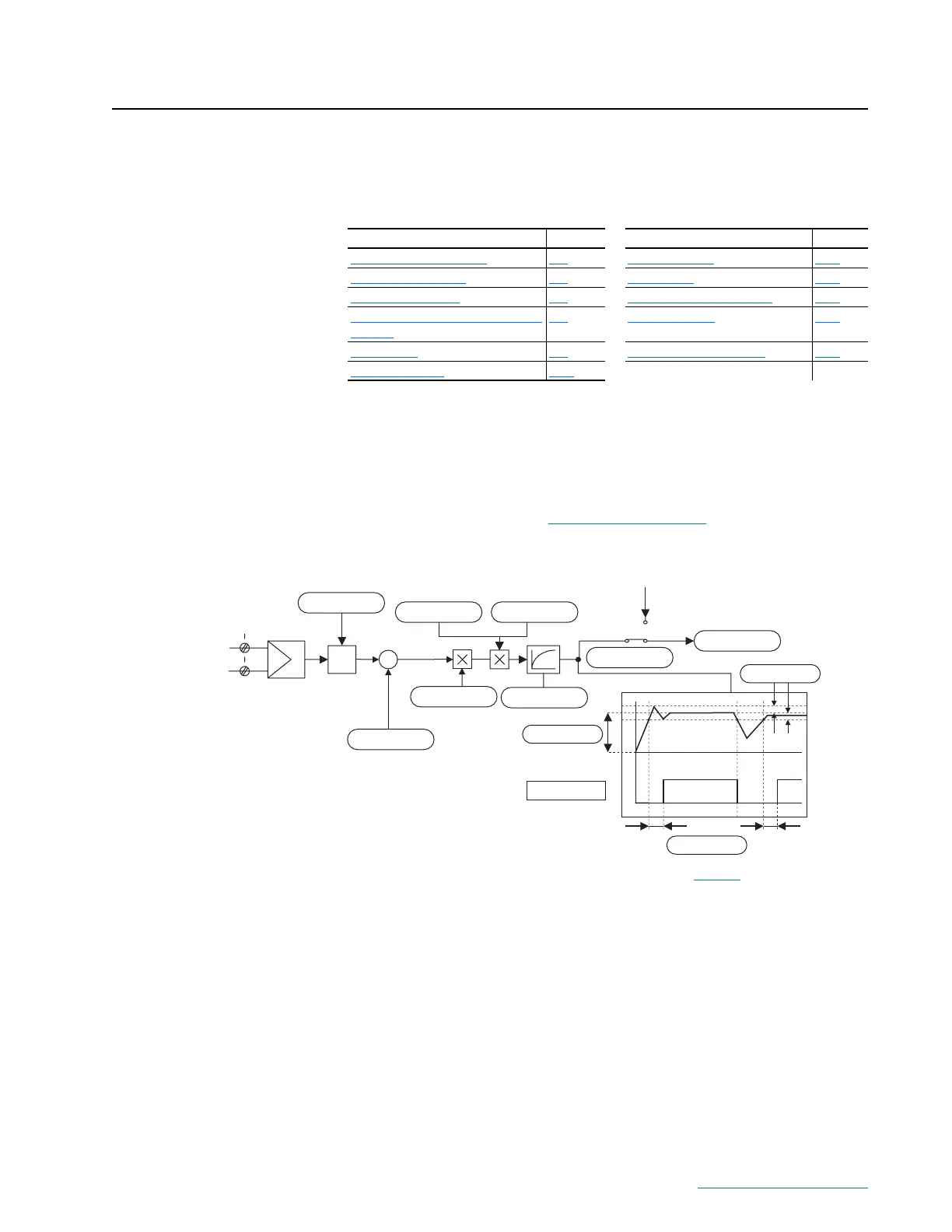
Analog Input Configuration
The analog inputs default to ±10V. To configure the analog inputs for
0-10V, set parameters [Anlg Inx Config] to 1, “0-10V”. To configure the
analog inputs for a current signal, set parameters [Anlg Inx Config] to 2, “0
- 20mA” or 3, “4 to 20mA”. In addition, switches S9, S10 and S11 must be
properly configured (refer to Table 1.L on page 1-33
for more information).
Example 1:
The speed reference value of a drive is defined with an external voltage of
5V. With this value the drive should reach the maximum allowable speed set
in Par 45 [Max Ref Speed]. Enter a scaling factor of 2 in [Anlg Inx Scale] to
scale the input voltage from 5V to 10V.
For information on . . See page For information on . . See page
Analog Input Configuration
C-1 Speed Feedback C-15
Current / Speed Curve C-4 Scale Blocks C-16
Droop Compensation C-5 Speed Regulation Functions C-17
Field Weakening Mode Configuration
(v1.006)
C-5 Start At Powerup C-24
PID Function C-8 Fine Tuning the Regulators C-25
Reference Control C-13
Σ
+
-
2
1
Volts
Ref_1-
Ref_1+
HW
input
type
Window comparator
F
From Digital Reference
Setting
Anlg In1 Cmp
0
0 ms
Anlg In1 Cmp Eq
Anlg In1 Cmp Dly
Anlg In1 Cmp Er
0
+/-10V
Anlg In1 Config
1
Ain1 Tune Scale
0
Anlg In1 Offset
1
Anlg In1 Scale
0
Anlg In1 Tune
0 ms
Anlg In 1 Filter
0
Anlg In1 Target
Speed Ref A
Anlg In1 Sel
Analog Input 1
Refer to the “Analog Inputs / Outputs & Mapping” block diagram on page D-4 for more information.
 Loading...


