PowerFlex Digital DC Drive User Manual - Publication 20P-UM001C-EN-P - July 2008
Supplemental Drive Information A-21
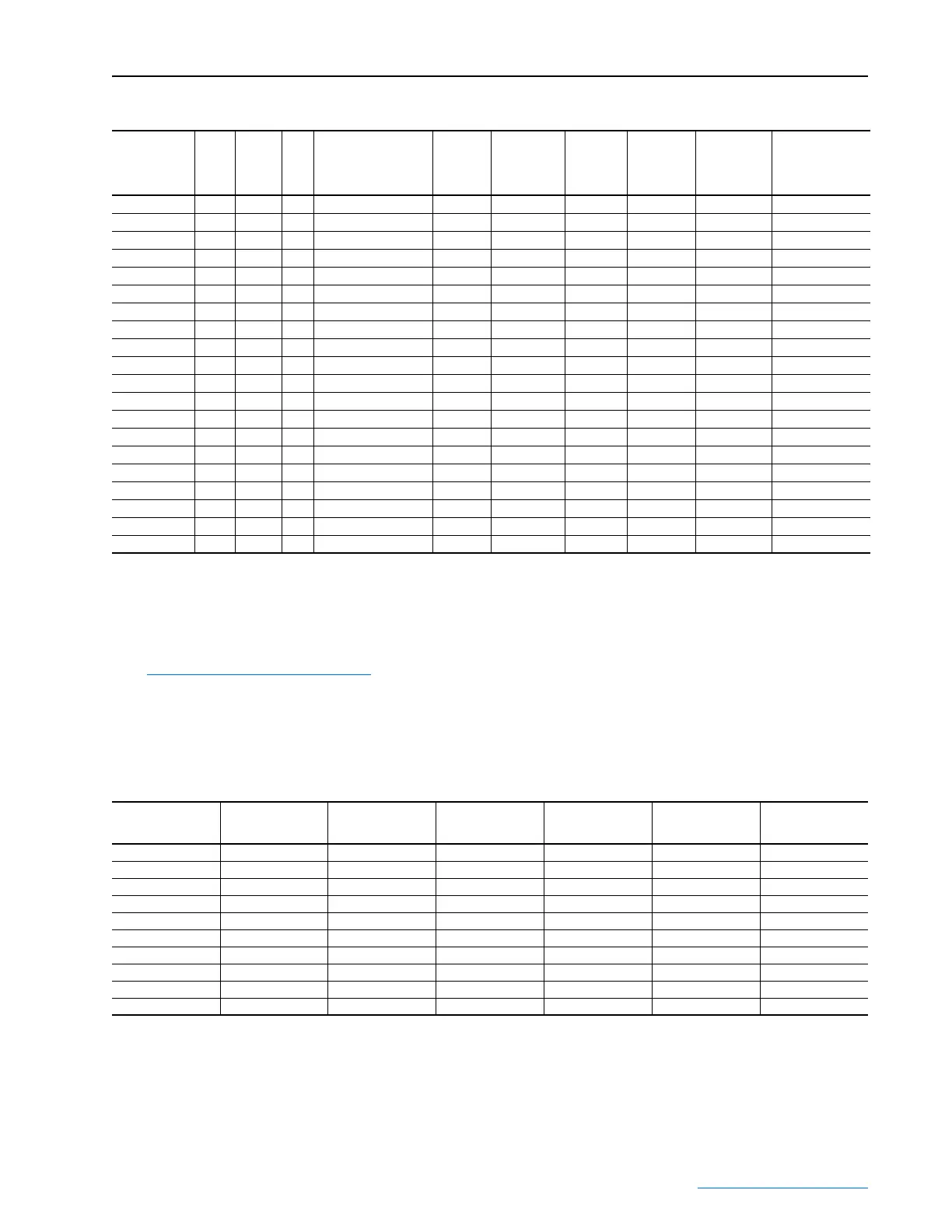
Table A.T 460V AC Input, Non-Regenerative Drives
DC Contactor Crimp Lug Kit
Specifications
Use the information provided in the table below to assist you in ordering the
correct Lug kit for your application.
Drive Cat. No.
DC
Amps
AC
Line
Amps HP
Dynamic Brake
Resistor Kit Cat. No.
Armature
Voltage
(Volts)
DB Resistor
Size (ohms)
DB
Resistor
Size
(Watts)
Brake
Amps
Required
DC Loop
Contactor
Cat. No.
(4)
DC Contactor
Crimp Lugs Cat.
No.
(9)
20P-21AD4P1 4.1 3.3 2 1370-DBH63 500 81 255 6.17 1370-DC56 1370-LG40
20P-21AD6P0 6 4.9 3 1370-DBH64 500 62 245 8.06 1370-DC56 1370-LG40
20P-21AD010 10 8.2 5 1370-DBH65 500 45 245 11.11 1370-DC56 1370-LG40
20P-21AD014 14 11.4 7.5 1370-DBH66 500 27 350 18.52 1370-DC56 1370-LG40
20P-21AD019 19 15.5 10 1370-DBH67 500 20 420 25.00 1370-DC56 1370-LG40
20P-21AD027 27 22.1 15 1370-DBH68 500 12 405 41.67 1370-DC56 1370-LG40
20P-21AD035 35 28.6 20 1370-DBH69 500 5 330 100.00 1370-DC56 1370-LG40
20P-21AD045 45 36.8 25 1370-DBH70 500 4.5 330 111.11 1370-DC56 1370-LG52
20P-21AD052 52 42.5 30 1370-DBH71 500 3.5 385 142.86 1370-DC56 1370-LG52
20P-21AD073 73 59.6 40 1370-DBH72 500 2.6 345 192.31 1370-DC110 1370-LG92
20P-21AD086 86 70.3 50 1370-DBH73 500 2 345 250.00 1370-DC110 1370-LG92
20P-21AD100 100 81.7 60 1370-DBH74 500 2 345 250.00 1370-DC110 1370-LG110
20P-21AD129 129 105.4 75 1370-DBH75 500 1 270 500.00 1370-DC180 1370-LG140
20P-21AD167 167 136.4 100 1370-DBH76 500 0.7 280 714.29 1370-DC180 1370-LG180
20P-21AD207 207 169.1 125 1370-DBH77 500 0.7 280 714.29 1370-DC280 1370-LG228
20P-21AD250 250 204.3 150 1370-DBH78 500 0.5 365 1000.00 1370-DC280 1370-LG268
20P-21AD330 330 269.6 200 1370-DBH79 500 0.7 280 714.29
(5) (10)
20P-21AD412 412 336.6 250
(1)
500 0.808 7292 –
(6) (10)
20P-21AD495 495 404.4 300
(2)
500 0.595 6069 –
(7) (10)
20P-21AD667 667 544.9 400
(3)
500 0.542 6439 –
(8) (10)
(1)
HUBBELL_Y95W808GB - Must be sourced separately from drive.
(2)
HUBBELL_Y101W595GB - Must be sourced separately from drive.
(3)
HUBBELL_Y109W542GB - Must be sourced separately from drive.
(4)
Coil voltage = 115V AC, 50/60Hz.
(5)
ABB_EHDB360C-1L-22 - ABB Contactor for drives with a dynamic brake. Must be sourcing separately from drive.
(6)
ABB_EHDB520C2P-1L - ABB contactor for drives with no dynamic brake. ABB_EHDB520C-1L - ABB contactor for drives with a dynamic brake. Must be sourced separately from drive.
(7)
ABB_EHDB650C2P-1L - ABB contactor for drives with no dynamic brake. ABB_EHDB650C-1L - ABB contactor for drives with a dynamic brake. Must be sourced separately from drive.
(8)
ABB_EHDB800C2P-1L - ABB contactor for drives with no dynamic brake. ABB_EHDB800C-1L - ABB contactor for drives with a dynamic brake. Must be sourced separately from drive.
(9)
See DC Contactor Crimp Lug Kit Specifications on page A-21 for more information.
(10)
Wire and Lug size dependant on Cabinet dims and local codes.
Rated Motor
Armature Current
(1)
A DC
DC Contactor Rating
A DC
Armature Conductor
Size
(2)
AWG
DB Conductor Size
(3)
AWG
Armature Conductor
Crimp Lug Hole Size
DB Conductor Crimp
Lug Hole Size
Lug Kit Catalog
Number
4.1 - 35 56 8 8 #10 #10 1370-LG40
45 - 52 56 6 8 #10 #10 1370-LG52
55 56 4 8 #10 #10 1370-LG56
60 - 86 110 2 6 0.25 in. 0.25 in. 1370-LG92
100 - 110 110 1/0 4 0.25 in. 0.25 in. 1370-LG110
129 180 2/0 2 0.3125 in. 0.3125 in. 1370-LG140
146 180 3/0 2 0.3125 in. 0.3125 in. 1370-LG160
147 - 167 180 4/0 2 0.3125 in. 0.3125 in. 1370-LG180
207 - 218 280 300MCM 1/0 0.5 in. 0.375 in. 1370-LG228
250 - 265 280 400MCM 2/0 0.5 in. 0.375 in. 1370-LG268
(1)
The Rated Motor Armature Current is taken directly from the motor nameplate or motor data. The current listed in this column is the maximum current allowed for the Armature Conductor
Size (column 3) and the DC Contactor Rating (column 2).
(2)
The armature conductors are sized by multiplying the Rated Motor Armature Current by 1.25 as provided for in NEC 420-22 (1987). The DC lug ratings are determined from NEC Table 310-16
(1987) for copper conductors, insulation temperature rated at 75° C (167° F) at an ambient temperature of 30° C (86° F). If conditions are other than shown in NEC Table 310-16, then refer
to application codes.
(3)
The dynamic braking (DB) conductors are sized as in footnote 2 above, but at half ampacity due to the short time duration of current flow in these conductors, and has been sized to satisfy
NEMA Standard ICS 3-302.62 - Dynamic Braking. If the load inertia is larger than that of the motor, calculations must be made to determine correct conductor sizing and DB resistor wattage
per NEMA Standard ICS 3-302.62.
 Loading...


