PowerFlex Digital DC Drive User Manual - Publication 20P-UM001C-EN-P - July 2008
1-28 Installation and Wiring
Control Circuit Input Power
The control circuit must be powered by an external 230V AC or 115V AC
single phase power supply. For frame B and C drives only, a jumper is
required between terminals SA and SB for 115V AC control input power.
For frame B drive SA-SB terminal block location, refer to Figure 1.26 on
page 1-29. For frame C drive SA-SB terminal block location, refer to Figure
1.27 on page 1-30.
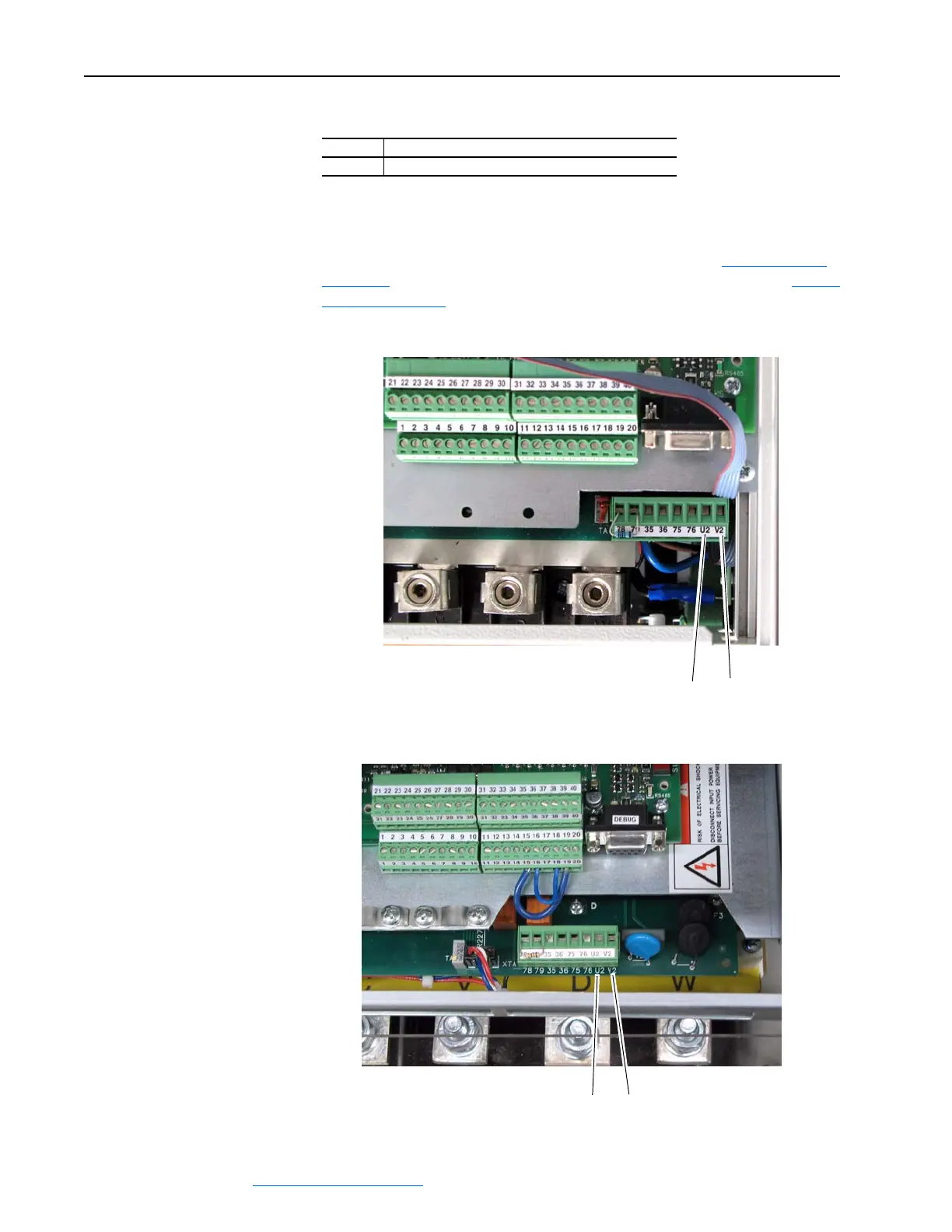
Figure 1.23 Frame A Control Circuit Terminal Block Location
Figure 1.24 Frame B Control Circuit Terminal Block Location
Terminals Description
U2, V2 Single phase AC power for the control circuits
U2 V2
U2 V2
 Loading...


