PowerFlex Digital DC Drive User Manual - Publication 20P-UM001C-EN-P - July 2008
1-24 Installation and Wiring
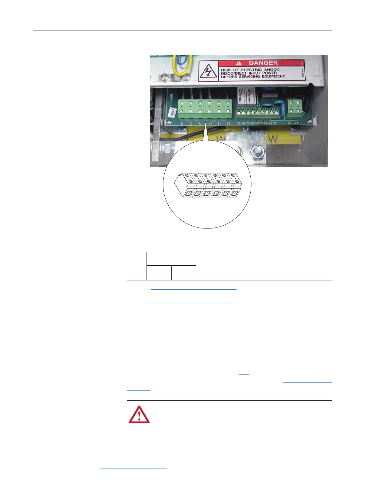
Figure 1.19 Frame C Field Circuit Terminal Block Location
Table 1.F Field Circuit Wire Sizes and Terminal Specifications
Field Current Resistors
The drive’s control circuit board is factory set to the minimum field current
rating based on the drive size. The setting of DIP switch S14 must be
changed to be ≥ the rated field current specified on the motor nameplate or
possible motor damage may result. In addition, the value selected with
switch S14 must be entered in parameter 374
[Drv Fld Brdg Cur] in the
control software when the drive is commissioned (refer to Drive Start Up on
page 2-1.)
V1U1C1D1
Front of drive
Frame
Drive Current Rating
Code
(1)
(1)
Refer to Catalog Number Explanation on page Preface-4, positions 8-10 for corresponding drive HP rating,
armature amp rating and field amp rating.
Terminals Wire Size and Type
(2)
(2)
See Cable and Wiring Recommendations on page 1-14 for more information.
Tightening Torque
(N
•m / lbs•in)230V 460V
All All All U1, V1, C1, D1
24-10 AWG/kcmils 0.5 - 0.8 / 4.4 - 7.1
!
ATTENTION: DIP switch S14 must be set to be ≥ the rated
field current specified on the motor nameplate or possible motor
damage may result.
 Loading...


