PowerFlex Digital DC Drive User Manual - Publication 20P-UM001C-EN-P - July 2008
3-60 Programming and Parameters
COMMUNICATIONS
Datalinks
610
611
[Data In A1] – Link A Word 1
[Data In A2] – Link A Word 2
Parameter number whose value will be written from a
communications device data table. The value will not be
updated until the drive is stopped.
Refer to your communications option manual for datalink
information.
Default:
Min/Max:
0 (0 = “Disabled”)
0 / 1408
612
613
[Data In B1] – Link B Word 1
[Data In B2] – Link B Word 2
See [Data In A1] – Link A Word 1
.
614
615
[Data In C1] – Link C Word 1
[Data In C2] – Link C Word 2
See [Data In A1] – Link A Word 1.
616
617
[Data In D1] – Link D Word 1
[Data In D2] – Link D Word 2
See [Data In A1] – Link A Word 1
.
618
619
[Data Out A1] – Link A Word 1
[Data Out A2] – Link A Word 2
Parameter number whose value will be written to a
communications device data table.
Default:
Min/Max:
0 (0 = “Disabled”)
0 / 1408
620
621
[Data Out B1] – Link B Word 1
[Data Out B2] – Link B Word 2
See [Data Out A1] – Link A Word 1
.
622
623
[Data Out C1] – Link C Word 1
[Data Out C2] – Link C Word 2
See [Data Out A1] – Link A Word 1
.
624
625
[Data Out D1] – Link D Word 1
[Data Out D2] – Link D Word 2
See [Data Out A1] – Link A Word 1
.
1319 [Data In Val Sel]
Selects the Datalink parameter register to display in Par 1320
[Data In Sel Data].
Default:
Min/Max:
610
610 / 617
1320
1320 [Data In SelData]
Displays the value selected in Par 1319 [Data In Val Sel].
Default:
Min/Max:
Read Only
- / +2
31
1319
Security
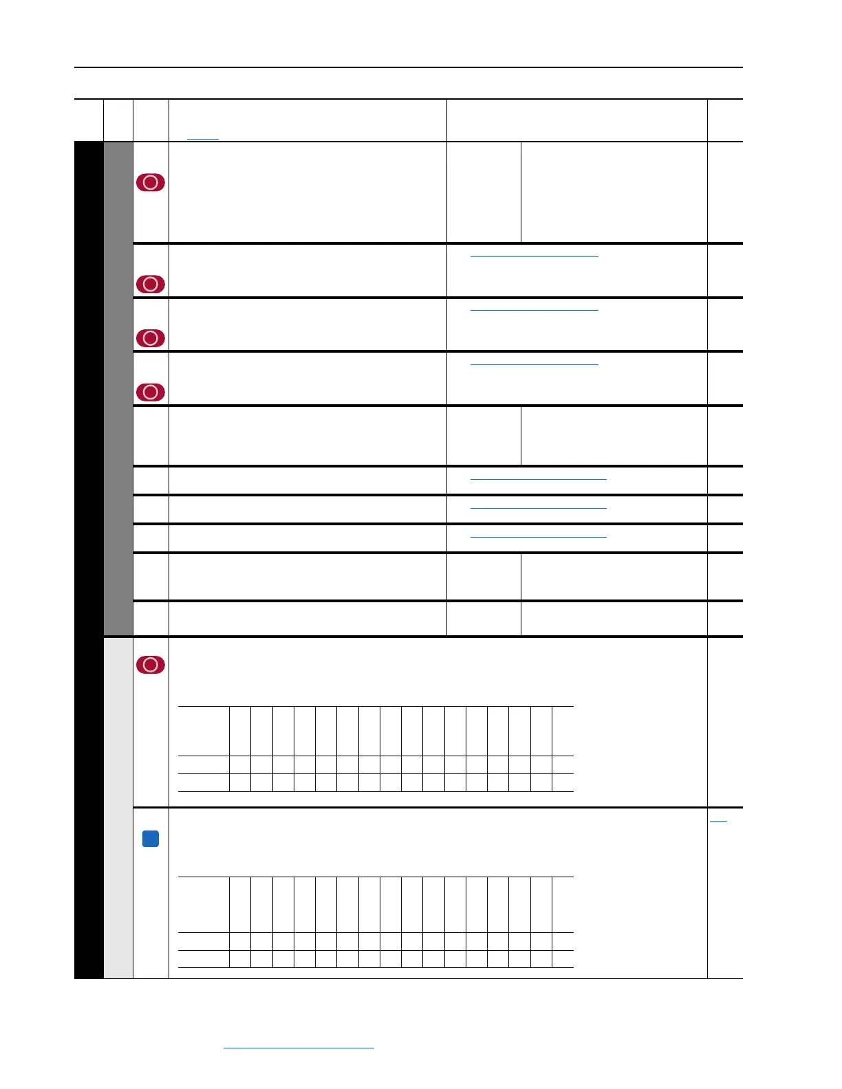
591 [Logic Mask]
Determines which ports can control the drive when Par 1377 [Write Mask Act], bit 15 is set to “1.” If the bit for a port is
set to “0,” the port will have no control functions except for stop. 0 = Control Masked, 1 = Control Permitted, x =
Reserved.
1376 [Logic Mask Act]
Indicates the status of the logic mask for the DPI ports. When bit 15 is set,
network security is controlling the logic mask instead of Par 591 [Logic Mask].
0 = Control Masked, 1 = Control Permitted, x = Reserved.
Read Only 591
File
Group
No.
Parameter Name & Description
See page 3-2 for symbol descriptions
Values
Related
Reserved
Reserved
Reserved
Reserved
Reserved
Reserved
Reserved
Reserved
Reserved
Reserved
DPI Port 5
DPI Port 4
DPI Port 3
DPI Port 2
DPI Port 1
Digital In
Default
xxxxxxxxxx111111
Bit
1514131211109876543210
A
Advanced
Aux Port 14
Aux Port 13
Aux Port 12
Aux Port 11
Aux Port 10
Aux Port 9
Aux Port 8
Aux Port 7
Reserved
DPI Port 5
DPI Port 4
DPI Port 3
DPI Port 2
DPI Port 1
Digital In
Default
0xxxxxxxxx111111
Bit
1514131211109876543210
 Loading...


