3-64 Programming and Parameters
PowerFlex Digital DC Drive User Manual - Publication 20P-UM001C-EN-P - July 2008
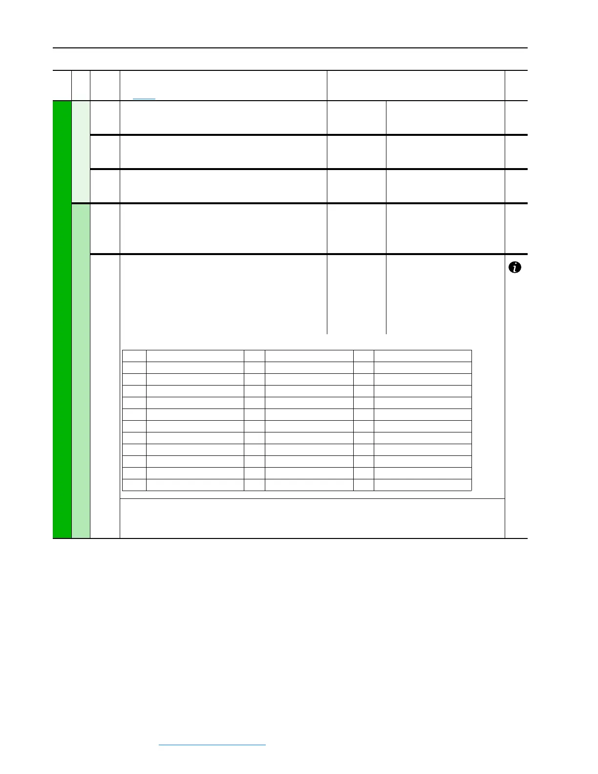
INPUT / OUTPUT
Analog Inputs
1404 [Analog In1 Value]
Value of the signal at analog input 1. Units based on the value
set in Par 71 [Anlg In1 Config].
Default:
Min/Max:
Units:
Read Only
-/+20.00
V or mA
71
1405 [Analog In2 Value]
Value of the signal at analog input 2. Units based on the value
set in Par 76 [Anlg In2 Config].
Default:
Min/Max:
Units:
Read Only
-/+20.00
V or mA
76
1406 [Analog In3 Value]
Value of the signal at analog input 3. Units based on the value
set in Par 81 [Anlg In3 Config].
Default:
Min/Max:
Units:
Read Only
-/+20.00
V or mA
81
Analog Outputs
62
63
64
65
[Anlg Out1 Scale]
[Anlg Out2 Scale]
[Anlg Out3 Scale]
[Anlg Out4 Scale]
Scaling of the analog outputs.
Default:
Min/Max:
1.00
–/ +10.00
66
67
68
69
[Anlg Out1 Sel]
[Anlg Out2 Sel]
[Anlg Out3 Sel]
[Anlg Out4 Sel]*
Selects the source of the value that drives the analog output.
*This parameter is used to configure the analog output on the
I/O Expansion circuit board.
Options:
Default:
Default:
Default:
Default:
12 =
13 =
18 =
14 =
“Motor Speed”
“Motor Curr”
“Fld Current”
“Motor Volts”
(1) ±10V = 100% of Par 45 [Max Ref Speed].
(2) ±10V = ± 200% of Par 179 [Nom Mtr Arm Amps].
(3) ±10V = ± 200% of Par 179 [Nom Mtr Arm Amps] x Par 233 [Output Voltage].
(4) As a percentage of Par 1153 [Max Diameter].
File
Group
No.
Parameter Name & Description
See page 3-2 for symbol descriptions
Values
Related
0 = “Off” (Not used) 12 = “Motor Speed” (Par 121)
(1)
24 = “Field Ref” (Par 500)
1 = “Spd Ref Out” (Par 385) 13 = “Motor Curr” (Par 199)
(2)
25 = “PID Output” (Par 774)
2 = “Trim Ramp” (Par 42) 14 = “Motor Volts” (Par 233) 26 = “Out Volt Lvl” (Par 921)
3 = “Ramp In” (Par 110) 15 = “Analog In 1” (Par 70) 27 = “Fld Cur Max” (Par 467)
4 = “Ramp Out” (Par 113) 16 = “Analog In 2” (Par 75) 28 = “Filtered Spd” (Par 924)
(1)
5 = “Spd Draw Out” (Par 1018) 17 = “Analog In 3” (Par 80) 29 = “Filtered Cur” (Par 928)
(2)
6 = “Trim Speed” (Par 43) 18 = “Fld Current” (Par 234) 30 = “Output Power” (Par 1052)
(3)
7 = “Spd Reg In” (Par 118) 19 = “UserDefined0” (Par 503) 31 = “Roll Diam” (Par 1154)
(4)
8 = “Spd Reg Out” (Par 236) 20 = “UserDefined1” (Par 504) 32 = “Tension Ref” (Par 1180)
9 = “Torque Ref” (Par 39) 21 = “UserDefined4” (Par 507) 33 = “Torque Curr” (Par 1193)
(2)
10 = “Trim Torque” (Par 40) 22 = “UserDefined5” (Par 508) 34 = “Winder Ref” (Par 1217)
(1)
11 = “Torq Reg In” (Par 41) 23 = “UserDefined6” (Par 509) 35 = “Active Comp” (Par 1213)
(2)
 Loading...


