2
2-7
1
2
10s
20s
ON
12
ON
12
ON
12
ON
12
ON
12
ON
12
ON
OFF
ON
OFF
ON
OFF
ON
OFF
ON
OFF
ON
OFF
(Wiring procedure)
(1) Connect the remote controller to the indoor unit remote controller wiring terminal plate (1, 2).
(Remote controller wiring)
(2) Connect the indoor units (U1, U2) and the outdoor units (1, 2). Connect the other outdoor units and indoor units
(with different refrigerant systems) in the same way. (Inter-unit control wiring)
Connect the remote controller communication wiring to the indoor units (U1, U2) for each refrigerant system.
(Interunit control wiring)
(3) Connect the remote controller communication wiring (2 wires) from the remote controller wiring terminal plate (1,
2) on the indoor unit (unit where the remote controller is connected) to the remote controller terminal plates (1,
2) on the other indoor units. (Remote controller communication wiring)
(4) Turn ON both the indoor and outdoor unit power and perform automatic address setting from the remote
controller. (For the automatic address setting procedure, refer to 2-8-4.)
NOTE
* Models with auxiliary heaters cannot be used for crossover wiring of the indoor unit power wires.
(Use a pull box to divide the wiring.)
Be sure to use the indoor unit temperature sensor (body sensor) when using this control. (Status at shipment.)
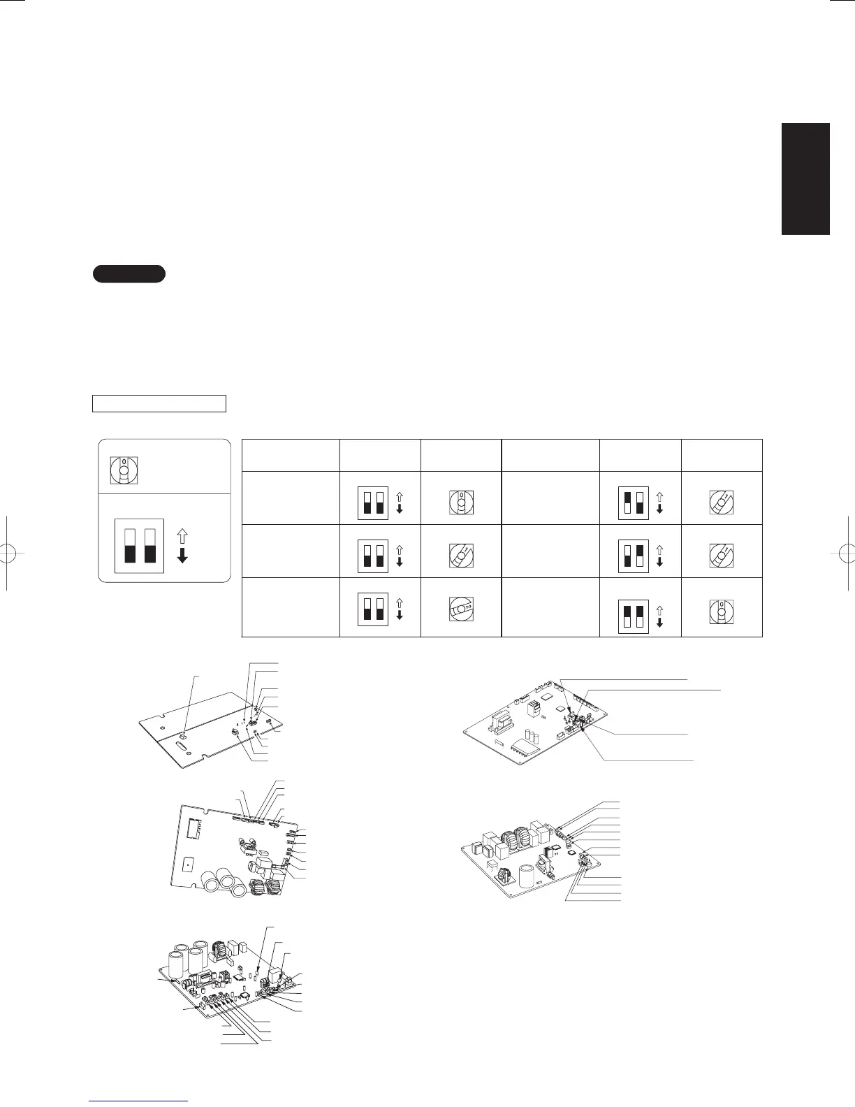
2-8-3. Setting the outdoor unit system addresses
For basic wiring diagram 2 (Set the system addresses: 1, 2, 3...)
System address rotary switch (Set to “0” at time of shipment)
System address rotary switch
System address
DIP switch
ON
System
address No.
System address
10s digit
(2P DIP switch)
System address
1s place
(Rotary switch)
0
Automatic address
(Setting at shipment = “0”)
1
(If outdoor unit is No. 1)
2
(If outdoor unit is No. 2)
11
(If outdoor unit is No. 11)
21
(If outdoor unit is No. 21)
30
(If outdoor unit is No. 30)
Both OFF
Both OFF
Both OFF
10s digit ON
20s digit ON
10s digit and 20s
digit ON
“0” setting
“1” setting
“2” setting
“1” setting
“0” setting
“1” setting
System
address No.
System address
10s digit
(2P DIP switch)
System address
1s place
(Rotary switch)
ON
OFF
Outdoor unit control PCB
Up side
HIC
Temperature
sensor
AUTO ADD (CN041)
System address
Rotary switch (S002)
TERMINAL (S010)
JP007
System address
DIP switch (S003)
RC-P (CN032,RED)
LED1
LED2
PUMP DOWN (CN042)
EEPROM (IC006)
TO (CN022, WHT)
Bottom
side
C2 (CN020, WHT)
MOV (CN25, WHT)
C1 (CN021, BLK)
TD, TS (CN023, WHT)
EXCT (CN026, RED)
SILENT (CN028, WHT)
RC-P (CN032, RED)
FAN (CN030, WHT)
ROM (CN012, WHT)
OC (CN013, BLU)
EMG (CN014, BRN)
20S (CN09, WHT)
FUSE (25A, F003)
SPW-C486VH
F101
MOV
(CN025, WHT)
TD (CN024, BLK)
TO (CN023, BLK)
TS (CN022, RED)
Varistor (VA002)
JP007
Varistor (VA001)
Terminal plug (CN015, BLK)
EMG (CN014, BRN)
OC (CN013, BLU)
ROM (CN012, WHT)
EEPROM (IC007)
PRY (CN110, YEL)
C2 (CN020, WHT)
C1 (CN021, WHT)
SPW-C256/366VH
System address rotary switch
Terminal plug (CN015, BLK)
OC (CN013, BLU)
EMG (CN014, BRN)
JP007
ROM (CN012, WHT)
EEPROM (IC007)
TD (CN024, BLK)
TO (CN023, BLK)
MOV(CN025, WHT)
SPW-C256/366VH8
SPW-C486/606VH8
System address 10s digit and 20s digit
DIP switch
Automatic address
button (black)
Terminal plug (black)
C2 (CN020, WHT)
C1 (CN021, WHT)
TS (CN022, RED)
Fig. 2-7
SM830160-03ClassicPAC-iA4.ind77SM830160-03ClassicPAC-iA4.ind77 2010/02/1610:28:092010/02/1610:28:09
 Loading...
