Figure: E
3.3 Electronics
Operation in standard I/O mode:
The sensors must be connected in a voltage-free state (U
v
= 0 V). The information in the
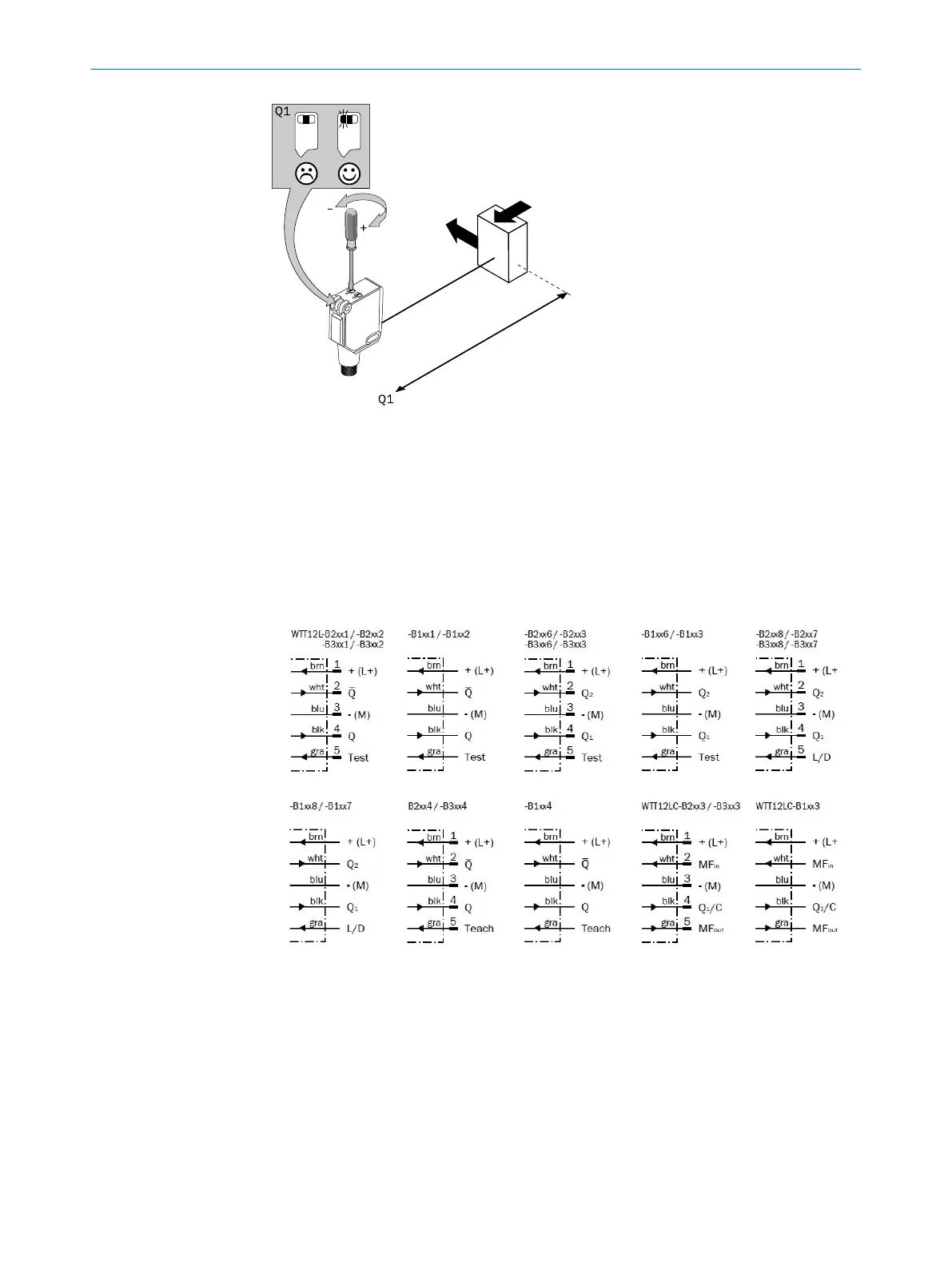
graphics [B] must be observed, depending on the connection type:
– Male connector connection: pin assignment
– Cable: core color
Figure 1: B
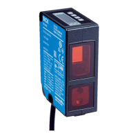
Only apply voltage/switch on the power supply (U
v
> 0 V) once all electrical connections
have been established. The green LED indicator lights up on the sensor.
Operation in IO-Link mode: Connect the device to a suitable IO-Link master and inte‐
grate in the master or control via IODD/function block. The green LED indicator flashes
on the sensor. IODD and function block are available to download from www.sick.com
under the order number.
Explanations of the connection diagram (Graphic B):
COMMISSIONING
3
8018110.1BVZ / 2021-05-18 | SICK
Subject to change without notice
7

 Loading...