Teach-in = external teach-in (ET) (see Adjustment)
TI / Test = test input (see Additional functions)
C = communication (e.g., IO-Link) (see Additional functions)
L/D = light/dark switch
3.4 Alignment
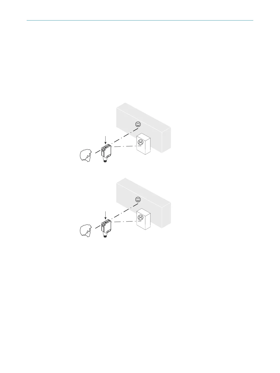
Align the sensor with the object. Select the position so that the red emitted light beam
hits the center of the object. You must ensure that the optical opening (front screen)
of the sensor is completely clear [E]. We recommend making the adjustments using an
object with a low remission.
Figure: E
Figure: E-2
4 Configuration
4.1 Adjustment
Sensor with potentiometer:
The sensing range is adjusted with the potentiometer (type: 4 rotations). Clockwise
rotation: sensing range increased; counterclockwise rotation: sensing range reduced.
We recommend placing the switching state in the object, e. g., see graphic E. Once the
sensing range has been adjusted, the object is removed from the path of the beam,
which causes the background to be suppressed and the switching output to change
(see graphic C).
Sensor with teach-in button:
3 COMMISSIONING
8
8018110.1BVZ / 2021-05-18 | SICK
Subject to change without notice

 Loading...