199/327
Building Technologies Basic Documentation LMV5... CC1P7550en
11 Description of connection terminals (AC 120 V) 22.05.2018
11 Description of connection terminals
(AC 120 V)
Terminal
marking
Connection symbol
Safety class
Input
Output
Description of connections Electrical rating
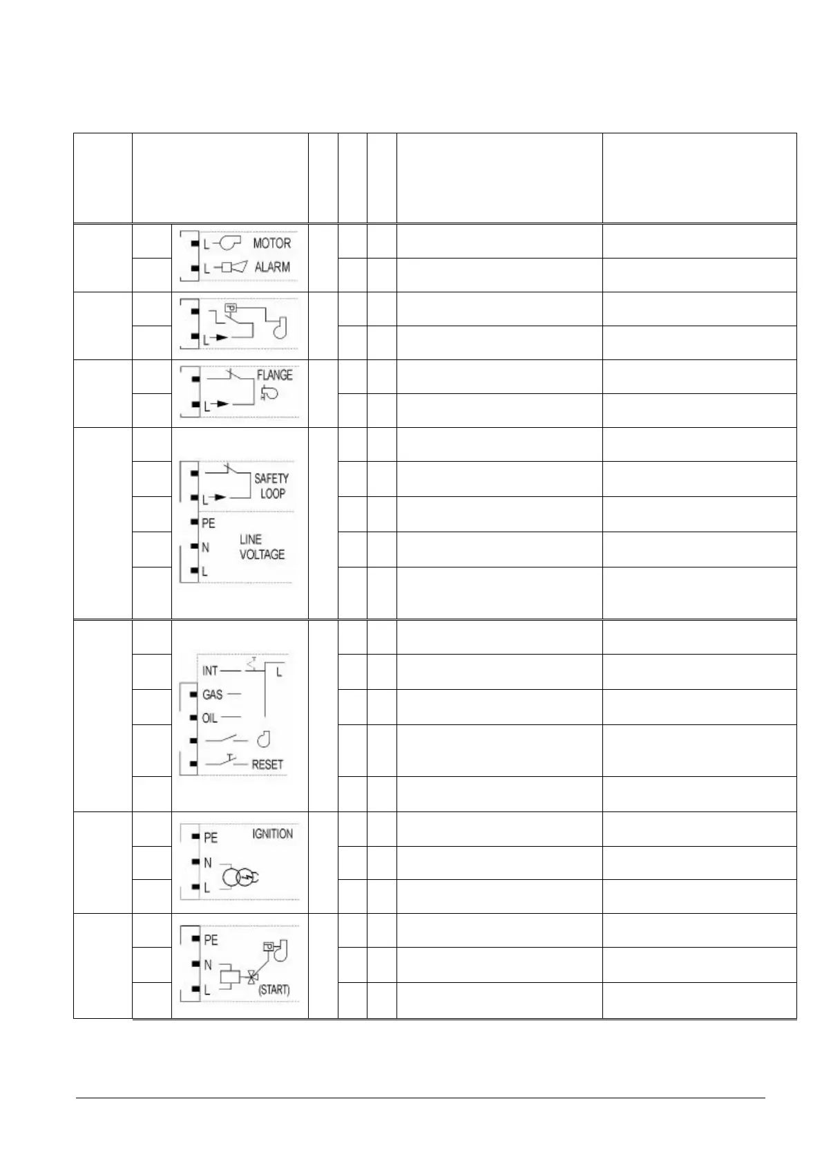
X3-01
PIN 1
I
˜ Fan motor contactor
AC 120 V +10 % / -15 %, 50...60 Hz,
1 A, (pilot duty), cosι 0.4
PIN 2 ˜ Alarm
AC 120 V +10 % / -15 %, 50...60 Hz,
1 A, (pilot duty), cosι 0.4
X3-02
PIN 1
I
˜ Air pressure switch (APS)
AC 120 V +10 % / -15 %, 50...60 Hz,
Imax 1.5 mA
PIN 2 ˜
Power signal for air pressure switch
(APS)
AC 120 V +10 % / -15 %, 50...60 Hz,
Imax 500 mA
X3-03
PIN 1
I
˜ End switch burner flange
AC 120 V +10 % / -15 %, 50...60 Hz,
Imax 5 A
PIN 2 ˜
Power signal for end switch burner
flange
AC 120 V +10 % / -15 %, 50...60 Hz,
Imax 5 A
X3-04
PIN 1
I
˜ Safety loop
AC 120 V +10 % / -15 %, 50...60 Hz,
Imax 5 A
PIN 2 ˜ Power signal for safety loop
AC 120 V +10 % / -15 %, 50...60 Hz,
Imax 5 A
PIN 3
˜ Protective earth (PE)
PIN 4
˜ Power supply neutral conductor (N)
PIN 5 ˜ Power supply live conductor (L)
AC 120 V +10% / -15%, 50...60 Hz,
fuse 6.3 AT
(DIN EN 60127 2 / 5)
X4-01
I
Fuel selection „internal“ if pin 1-2 is not
used
PIN 1 ˜ Fuel selection gas
AC 120 V +10 % / -15 %, 50...60 Hz,
Imax 1.5 mA
PIN 2 ˜ Fuel selection oil
AC 120 V +10 % / -15 %, 50...60 Hz,
Imax 1.5 mA
PIN 3 ˜
Fan contactor contact (FCC) or
flue gas recirculation power switch
(FGR-PS)
AC 120 V +10 % / -15 %, 50...60 Hz,
Imax 1.5 mA
PIN 4 ˜ Reset / manual lockout
AC 120 V +10 % / -15 %, 50...60 Hz,
Imax 1.5 mA
X4-02
PIN 1
I
˜ Protective earth (PE)
PIN 2
˜ Neutral conductor (N)
PIN 3 ˜ Ignition
AC 120 V +10 % / -15 %, 50...60 Hz,
1.6 A, (pilot duty), cosι 0.2
X4-03
PIN 1
I
˜ Protective earth (PE)
PIN 2
˜ Neutral conductor (N)
PIN 3 ˜
Start signal or pressure switch-relief
valve
AC 120 V +10 % / -15 %, 50...60 Hz,
75 VA, (pilot duty), cosι 0.4
 Loading...

