22/327
Building Technologies Basic Documentation LMV5... CC1P7550en
2 General 22.05.2018
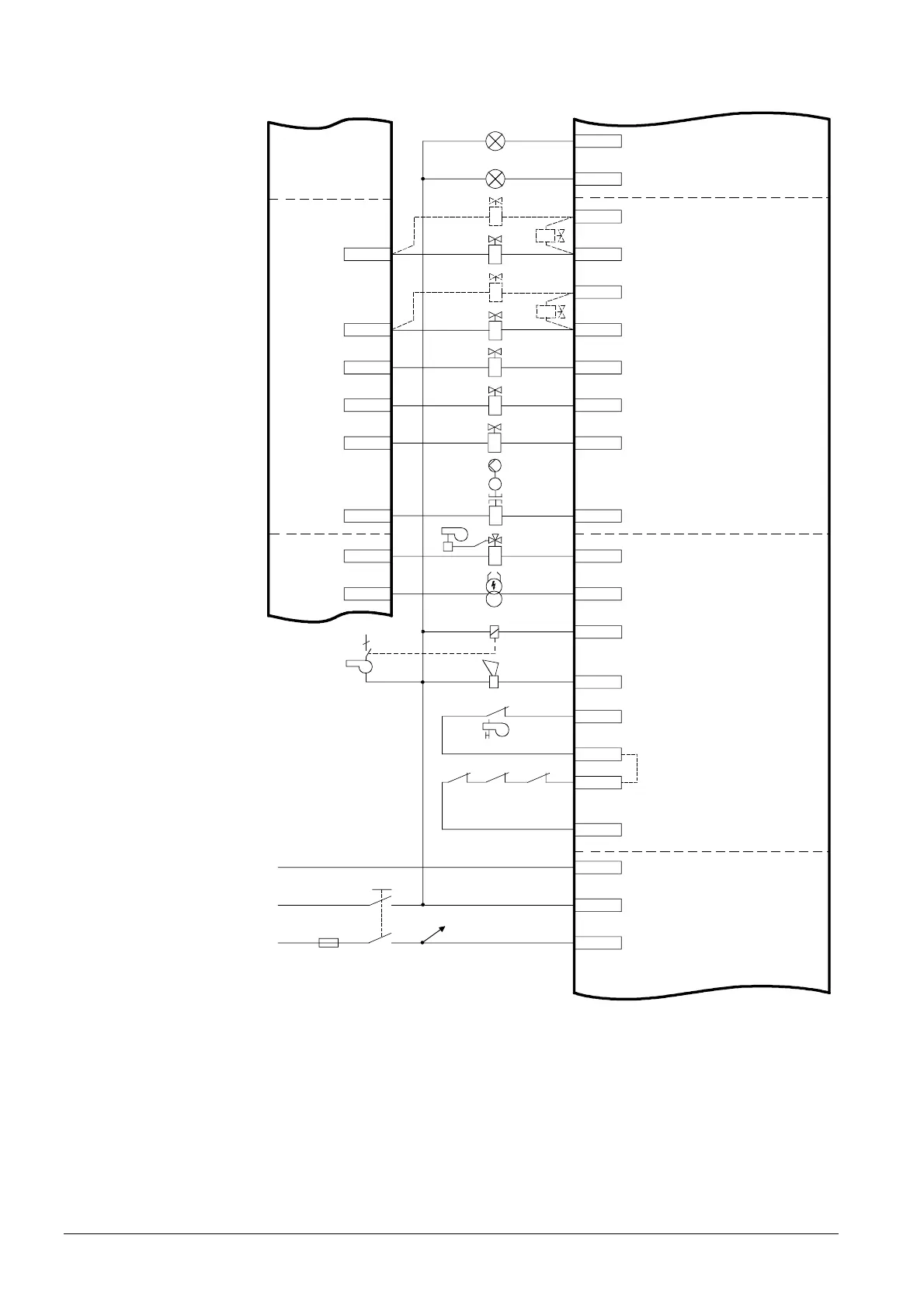
2.2 Block diagram of inputs / outputs
X3-04.3
X3-04.5 Power supply live conductor (L)
X3-04.4 Power supply neutral conductor (N)
Protective earth (PE)
X3-04.2 Power signal for safety loop
X3-04.1
Safety loop
X3-03.2 Power signal for end switch burner flange
X3-03.1
End switch burner flange
(part of safety loop)
X3-01.2 Alarm
X3-01.1 Fan motor contactor
IgnitionX4-02.3
Start signal or PS relief (APS test valve)X4-03.3
Oil pump / magnetic clutchX6-02.3
Fuel valve SV (OIL)X6-03.3
Fuel valve V2 (OIL)X7-01.3
Fuel valve V3 (OIL)X7-02.3
Fuel valve V1 (OIL)
X8-02.1
Auxiliary terminal for valves connected in seriesX8-02.2
Fuel valve V1 (OIL)X8-03.1
Auxiliary terminal for valves connected in seriesX8-03.2
Signal lamp oil
X8-01.2
Signal lamp gasX8-01.1
X4-02.2
X4-03.2
X6-02.2
X6-03.2
X7-01.2
X7-02.2
X8-02.3
X8-03.3
M
P
SLT AUX
WATER-
SHORTAGE
L1-L3
FAN
PE
N
L1
F 6.3 AT
L1'
OIL
OIL + GAS
OIL + GAS
LMV5...
LMV5...
3
755 0a10e /090 3
Figure 4: Block diagram – inputs / outputs
 Loading...

