20/327
Building Technologies Basic Documentation LMV5... CC1P7550en
2 22.05.2018
2 General
2.1 Brief description
The LMV5 is a microprocessor-based burner management system with matching
system components for the control and supervision of forced draft burners of medium to
high capacity.
The following components are integrated in the LMV5:
∂ Burner control with gas valve proving system
∂ Electronic fuel-air ratio control for:
- A maximum of 4 actuators for LMV50 / LMV51
- A maximum of 6 actuators for LMV52
∂ Optional PID temperature or pressure controller (boiler controller / load controller)
∂ Optional VSD module
The system components (AZL5, actuators, PLL52, etc.) are interconnected via a bus
system. Communication between the bus users takes place via a safety-related,
system-bound data bus (for safety reasons, integration of the bus into external CAN
bus systems is not possible). All safety-related digital outputs of the system are
permanently monitored via a contact feedback network.
For flame supervision in connection with the LMV5 and continuous operation, the QRI
infrared flame detector, the QRA7 flame detector, or an ionization probe can be used
and, for intermittent operation, the optical flame detectors of type QRB / QRA2 / QRA4 /
QRA10 with AGQ1 (120 V~/230 V~ mains connection).
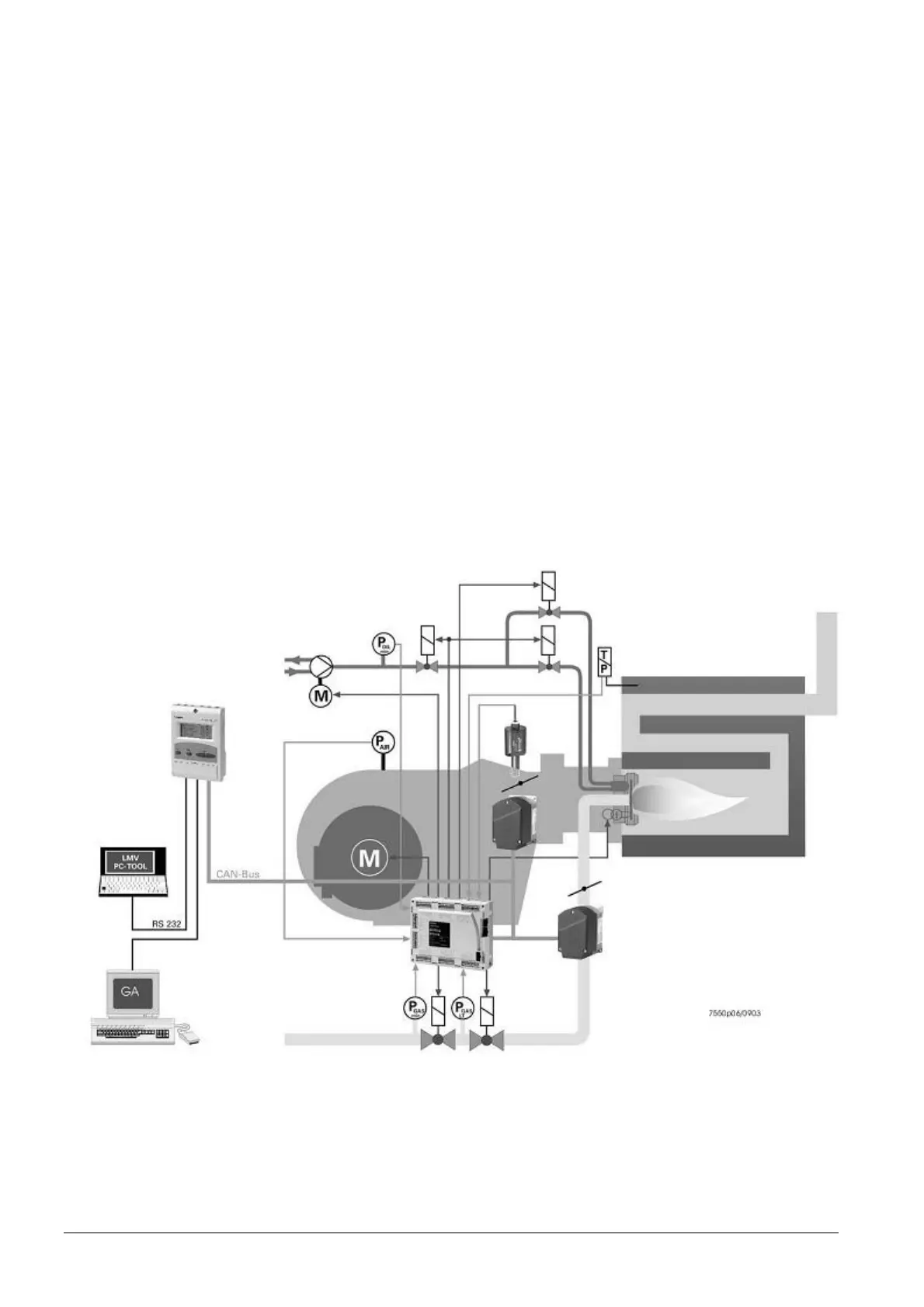
Figure 3: Basic diagram
Example:
Dual-fuel burner
∂ Gas: Modulating
∂ Oil: 2-stage
 Loading...

