Programming Example for Standard Function Blocks
9.5 Example "Printing" and "Reading and Controlling the CP 340 Inputs/Outputs"
PtP coupling and configuration of CP 340
Manual, 04/2011, A5E00369892-03
153
9.5 Example "Printing" and "Reading and Controlling the CP 340
Inputs/Outputs"
Introduction
The inputs and outputs are mapped to memory bits at the beginning and end of OB 1. Only
the memory bits are used in the test program.
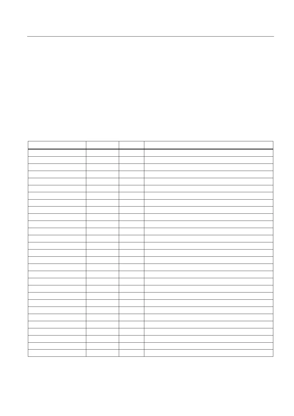
Inputs and outputs used for FC 5 and FC 6
The assignment of the inputs/outputs to memory bits is shown in the table below.
Symbol Input/output Flag Comment
ANW_RECH I 0.0 M 0.0 "0" signal
ANW_DRUCK I 0.1 M 0.1 "1" = select "printing" and "control/status"
RESET_SP I 0.2 M 0.2 Start RESET PRINT
I 0.3 M 0.3 Free
I 0.4 M 0.4 Free
I 0.5 M 0.5 Free
REQ_SP I 0.6 M 0.6 Start PRINT job
EN_R_R I 0.7 M 0.7 Execute SET job
AUFTR_1_DR I 1.0 M 1.0 Print job selection; "1" = job 1
AUFTR_2_DR I 1.1 M 1.1 Print job selection; "1" = job 2
AUFTR_3_DR I 1.2 M 1.2 Print job selection; "1" = job 3
AUFTR_4_DR I 1.3 M 1.3 Print job selection; "1" = job 4
I 1.4 M 1.4 Free
I 1.5 M 1.5 Free
STEU_DTR I 1.6 M 1.6 Control signal DTR, signal for V24_SET FC
STEU_RTS I 1.7 M 1.7 Control signal RTS, signal for V24_SET FC
Display FB parameter
A_DONE_SP Q 4.0 M 8.0 PRINT DONE
A_BIE_SP Q 4.2 M 8.2 PRINT binary result
Q 4.3 M 8.3 "0"
Q 4.4 M 8.4 "0"
Q 4.5 M 8.5 "0"
Q 4.6 M 8.6 "0"
Q 4.7 M 8.7 "0"
A_V24_STAT_DTR_OUT Q 5.0 M 9.0 STAT_DTR_OUT
A_V24_STAT_DSR_IN Q 5.1 M 9.1 STAT_DSR_IN
A_V24_STAT_RTS_OUT Q 5.2 M 9.2 STAT_RTS_OUT
A_V24_STAT_CTS_IN Q 5.3 M 9.3 STAT_CTS_IN
A_V24_STAT_DCD_IN Q 5.4 M 9.4 STAT_DCD_IN