PtP coupling and configuration of CP 340
Manual, 04/2011, A5E00369892-03
165
Connecting Cables
B
B.1 RS 232C interface of the CP 340–RS 232C
Pin assignment
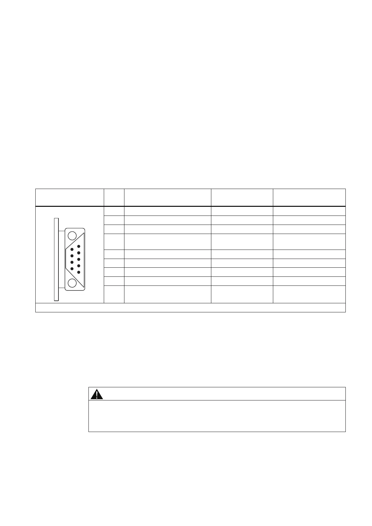
The table below shows the pin assignment for the 9-pin sub-D male connector in the front
panel of the CP 340-RS 232C.
Table B- 1 Pin assignment for the 9-pin sub-D male connector of the integrated interface of the CP 340-RS 232C
Male Connector on CP
340-RS 2323C
*
Pin Designation Input/Output Meaning
1 DCD Received Detector Input Receiver signal level
2 RXD Received Data Input Received data
3 TXD Transmitted Data Output Transmitted data
4 DTR Data Terminal Ready Output Communication terminals
ready
5 GND Ground - Signal ground (GND
int
)
6 DSR Data Set Ready Input Ready for operation
7 RTS Request To Send Output Activate transmitter
8 CTS Clear To Send Input Ready for sending
9 RI Ring Indicator Input Receiving call
* View from the front
Connecting cables
If you make your own connecting cables you must remember that unconnected inputs at the
communication partner may have to be connected to open-circuit potential.
Please note that you must only use shielded connector casings. A large surface area of both
sides of the cable shield must be in contact with the connector casing. You are advised to
use Siemens V42 254 shielded connector casings.
CAUTION
Never connect the cable shield with the GND, as this could destroy the submodules.
GND must always be connected on both sides (pin 5), otherwise the submodules could
again be destroyed.

 Loading...


