Electrical connection
6.1 Connecting the machine
1MB..1/2/3/4 - shaft heights 63 ... 355
Operating Instructions, 06/2020, A5E44455710A
73
6.1.1.3 Terminal marking
According to IEC / EN 60034-8, the following basic definitions apply to the terminal markings
for 3-phase machines:
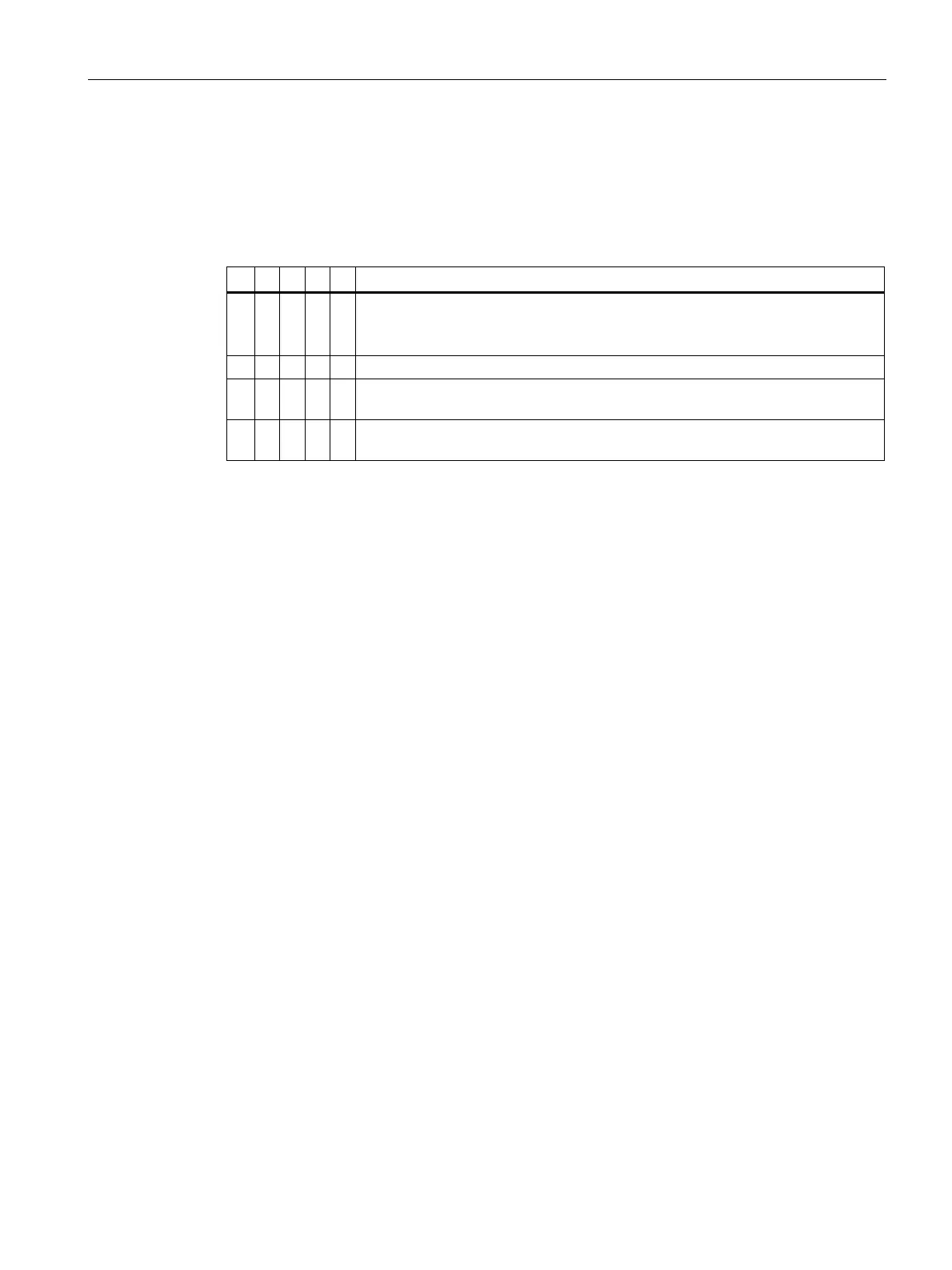
Table 6- 1 Terminal markings using the 1U1-1 as an example
x Code for split winding, where applicable. Special case for pole assignment for
pole-changing machines.
A lower index signifies a lower speed.
Phase designation U, V, W
x Index for winding start (1) or end (2) or if there is more than one connection per
x Additional indices for cases in which it is obligatory to connect parallel power
feed cables to several terminals with otherwise identical markings
6.1.1.4 Additional bores in the terminal box
Additional bores in the terminal box must be drilled by the manufacturer or by a specialist
workshop for electrical machinery that has been authorized by the manufacturer.
6.1.1.5 Cable entry
Certified cable entries, thread adapters and sealing plugs
Only use sealing plugs, cable glands and conductor glands or thread adapters that are
suitable, certified and marked for use in the respective explosion protection type and degree
of protection (IEC / EN 60079-14).
Terminal box
The number and size of the cable entry tapped holes is provided in the machine dimension
drawing.
Inserting cables into the terminal box
1. Only use cable entries that are suitable for the cables.
2. Only use cable entries and cables suitable for the prevailing ambient temperature.
3. Ensure that the power cables are strain relieved when inserting them in the terminal box.
4. Carefully connect the cables and ensure a reliable protective conductor connection.
5. Tighten the glands and the elements for the strain relief with the torque specified by the
manufacturer.
 Loading...