Descriptions of the PLC subroutines
3.13 Subroutine 40 - AXIS_CTL (controlling the spindle and axes)
PLC Subroutines Manual
42 Operating Instructions, 12/2012, 6FC5397-2EP10-0BA0
3.13 Subroutine 40 - AXIS_CTL (controlling the spindle and axes)
Purpose
Subroutine 40 is used to control the drive pulse enable (DB380xDBX4001.7) and controller
enable (DB380xDBX2.1), monitoring the hardware limits and the reference cam signals, and
controlling the enable signal for the spindle according to a spindle command (for example,
SPINDLE CW, SPINDLE CCW, Mo3, M04, SPOS, etc.). The motor brake is automatically
controlled by the SINAMICS V60 drives.
This subroutine provides two ways to realize the hardware limit control:
● PLC solution (MD14512 [18] bit 6 = 0)
Each feed axis has one (MD14512 [18] bit 7 = 1) or two (MD14512 [18] bit 7 = 0)
hardware limit switches. This subroutine activates the NCK hardware limit function via the
NCK interface DB380xDBX1000.0 or DB380xDBX1000.1 according to the configurations
of the hardware limit switches, and thus makes the NCK produce a feed stop signal to an
over-distance axis.
Furthermore, you can also connect the output OVlmt of this subroutine with the input
HWL_ON of subroutine 33 to activate the Emergency Stop automatically once the
hardware limit of any axis has been reached.
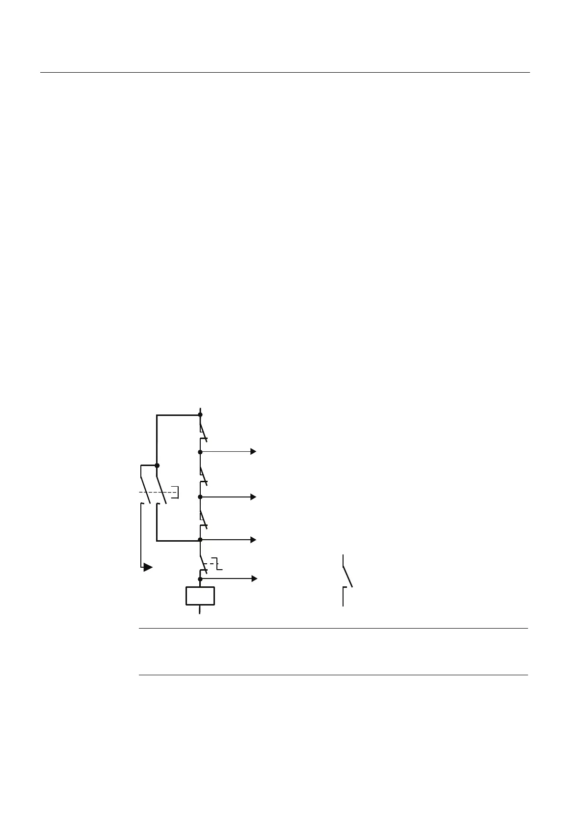
● Hardware solution (MD14512 [18] bit 6 = 1)
This solution is independent of the PLC and thus is much safer:
9
UGD[LVVZWLFK
QGD[LVVZWLFK
,QSXWWR
_3LMTp
,QSXWWR
_2LMTp
,QSXWWR
_1LMTp
,QSXWWR
_OVLrel
5HOHDVH
EXWWRQ
,QSXWWR
E_Key
VWD[LVVZWLFK
7HUPLQDORIWKH
6,1$0,&69
(PHUJHQF\6WRS
9'&
9
KA1
KA1
Note
The connection between the terminal 65 of the SINAMICS V60 and the +24 V signal is
cut off automatically at any of the hardware limits or an EMERGENCY STOP.

 Loading...


