Descriptions of the PLC subroutines
3.24 Subroutine 51 - Turret1_HED_T (turret with Hall effect device position sensor)
PLC Subroutines Manual
58 Operating Instructions, 12/2012, 6FC5397-2EP10-0BA0
Assigned global variables
None
Relevant PLC machine data
None
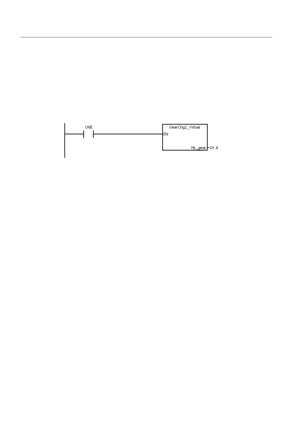
Example for calling subroutine 50
3.24 Subroutine 51 - Turret1_HED_T (turret with Hall effect device
position sensor)
Purpose
Subroutine 51 is used to control the turret with a Hall effect device positioning sensor, and
the turret motor is controlled by the PLC.
The turret rotates clockwise to search for a tool, and rotates counter-clockwise after
positioning the desired tool to clamp it (the turret CCW rotation time can be adjusted). An
alarm occurs if the turret fails to position the desired tool after the duration expires. The
subroutine verifies the time that the turret rotates CCW, and sets a limit of maximum 3
seconds for this rotation time to prevent the turret motor from being broken.
In the AUTO and MDA modes, the T function starts a tool change operation. In the JOG
mode, a short strike on the MCP key changes a turret position.
During a tool change, the NC interface signals "Read-in disable" (DB3200.DBX6.1) and
"Feedhold" (DB3200.DBX6.0) are set; this means that the part program can only continue to
run after the tool change.
The turret positioning is prohibited in the case of an Emergency Stop, turret motor overload
or program test/simulation.
The timing diagram for positioning a tool in the turret using the Hall effect device positioning
sensor is shown as follows:

 Loading...


