6 General Repair
6C Foot Controls Repair
6 - 36
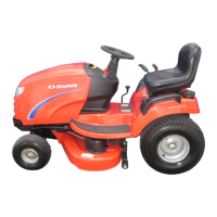
Figure C–9. Clutch Rod Cotter Pin & Washer
8.If no additional service is to be performed, reassemble
remaining parts in reverse order of disassembly. See
Figures C–11 through C-13 for correct parts position-
ing after reassembly, and check for proper operation
of brake pedal assembly parts. If additional service
in this area is required, continue to next section.
Clutch Rod Service
The clutch rod extends from the foot pedal arm through
the slot in the guide rod/brake rod assembly, to the idler
arm assembly, and is held in place at both ends by cotter
pins. (See Figures C–6 & C–9)
Once the foot pedal assembly has been removed, the
foot pedal arm/parking brake cam/switch actuator/ clutch
rod assembly can be removed from the unit as an
assembled group for bench inspection and any required
repair or replacement:
NOTE: The lift cam (Figure C–8) remains attached to
the upper lift link. See Hand Controls Section for part
position and placement.
1. Using a needle-nose pliers, remove the cotter pin that
secures the parking brake rod to the parking brake
cam (Figure C–9). (The parking brake cam uses the
front end of the clutch rod as a pivot point, and must
be separated from the parking brake rod to permit
removal of the clutch rod and related parts as a
group.)
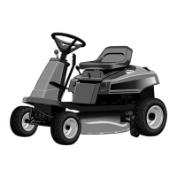
2. Remove the cotter pin and washer that secure the
rear end of the clutch rod to the idler arm (Figure
C–9). The clutch rod and related parts can now be
removed from the unit for inspection and any neces-
sary repair.
3. Check all parts for signs of wear, corrosion, or dam-
age, and replace individual parts as required. Before
disassembling, note the assembly position of all
parts.
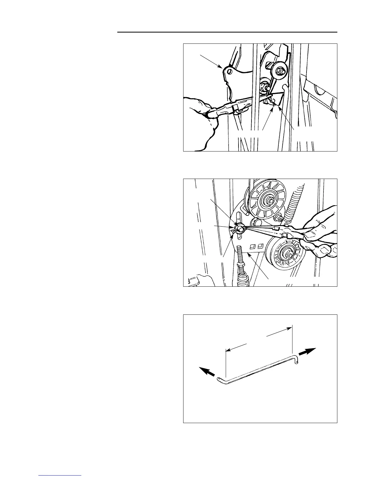
4. Hydro Modles only: The clutch rod must be straight
between the bends at each end (Figure C–10). If the
clutch rod is bent or damaged, remove the cotter pin
and washer that secure it to the foot pedal arm/park-
ing brake cam, and replace it.
5. Reassemble all parts in reverse order of disassem-
bly, and check for free movement before reinstalling
the clutch rod parts on the unit.
6. When reinstalling rear end of clutch rod to idler arm
assembly, be sure to insert the clutch rod end
through the hole in the guide rod/brake rod located
under the idler arm before inserting the rod end into
the slot in the idler arm. If no additional service is to
be performed, check foot pedal arm and parking
brake rod for proper operation.
Figure C–8. Remove Parking Brake Rod Cotter Pin
& Washer (Assembled Position Shown)
Figure C–10. Check Clutch Rod (Hydro Models Only)
Clutch
Rod
Cotter Pin
Straight
To Idler Arm
Assembly
Cotter Pin
Washer
Idler Arm Assembly
To Foot
Pedal Arm
Lift Cam
Parking
Brake Cam
 Loading...