4 Adjustments
Electric PTO
4 - 2
Electric PTO Clutch
Adjustment
Adjustment of the PTO clutch is usually not necessary on
new units.
1. Remove key from ignition switch and disconnect
spark plug wires to prevent the possibility of acciden-
tal starting while the PTO is being adjusted.
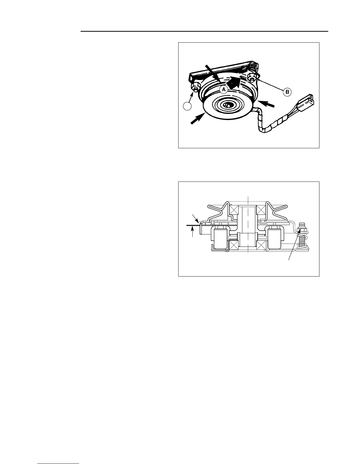
2. See Figure 1. Note the position of the 3 adjustment
windows (A) in the side of the brake plate, then rotate
the pulley so that each of the three rivet joints (visible
inside the gap between the pulley and the brake
plate) is positioned approximately midway between
the three adjustment windows.
3. Insert a .012” feeler gauge through each window,
positioning the gauge between the rotor face and the
armature face as shown in Figure 2.
4. With all three feeler gauges in place, alternately tight-
en the adjustment nuts (B, Figure 1) until the rotor
face and armature face just contact the gauges.
5. Check the gauges for an equal amount of tension
when inserted and removed, and make any neces-
sary adjustments by tightening or loosening the
adjustment nuts.
6. Remove the feeler gauges.
NOTE: The actual air gap between the rotor and arma-
ture may vary even after performing the adjustment pro-
cedure. This is due to dimensional variations on compo-
nent parts, and is an acceptable condition.
8. Check the mower blade stopping time. The mower
blades and mower drive belt should come to a com-
plete stop within five seconds after the electric PTO
switch is turned off.
Figure 1. PTO Clutch Adjustment
A. Adjustment Window (Qty. 3, one shown)
B. Adjustment Nut (Qty. 3, two shown)
Rivet
Rivet
Rivet
Window
Adjustment Nut
Figure 2. Feeler Gauge Position
.012”
Feeler
Gauge
(3) Req’d
B
 Loading...