7 Transmission Repair
7D Hydro-Gear 0750 / 0800
7 - 90
Assembly
Important Notes:
All parts should be thoroughly cleaned in a suitable sol-
vent. All sealant material MUST be removed from the
housing halves prior to reassembly.
Inspect all parts for damage, nicks or unusual wear pat-
terns. Replace all parts having unusual, excessive wear
or discoloration.
Inspect the sealing surfaces, bearing surfaces and shaft
spline. Polish the sealing areas on the shafts, if neces-
sary. Replace any worn or damaged parts.
The running surfaces of the cylinder blocks MUST be flat
and free from scratches. If scratches or wear are found
on the running surface of the cylinder block or center
section, polish or replace the parts. When polishing
these surfaces, up to 0.0004 in. may be removed. If this
is not sufficient to obtain a flat surface free of scratches,
the part should be replaced.
Clean and lightly oil parts prior to assembly of the
transaxle.
NOTE: Be sure to torque all threaded parts to the recom-
mended torque levels and replace all o-rings and shaft
seals.
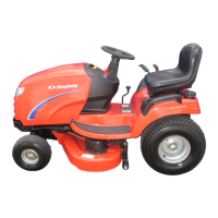
1. Install the displacement control shaft. See Figure
D–26.
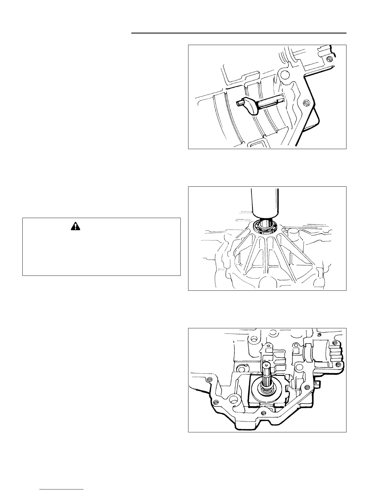
2. Install the pump input shaft assembly and retaining
ring into the housing. See Figure D–27.
3. Install the pump shaft lip seal.
4. Reposition the upper housing and install the swash-
plate cradle bearings.
5. Install the slot guide block onto the displacement con-
trol shaft.
6. Install the swashplate assembly into the housing. The
slot on the swashplate must engage the slot guide
block on the displacement control shaft. Use a tool
such as a screwdriver to hold the guide block in posi-
tion while installing the swashplate.
NOTE: Be sure the thick race of the pump thrust bearing
is toward the pistons.
7. Install the thrust washer and pump block spring onto
the pump shaft.
WARNING
Most parts have critical tight tolerance surfaces.
Care must be exercised to prevent damage to
these surfaces during assembly. Protect
exposed surfaces, openings and ports from
damage or foreign material.
Figure D–26. Install Displacement Control Shaft
Figure D–27. Install Pump Shaft Assembly
Figure D–28. Swashplate Installation
 Loading...