6 - 21
6 General Repair
6B Hand Controls Repair
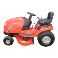
Figure B–8. Broadmoor Hydro Shift/Lift Lever
Access Area
Shift Lever Assembly Service
Shift lever assembly service requires that the dashboard
be removed. Refer to the Hood, Dash, and Grill Repair
section for dashboard removal instructions.
After the dash assembly is fully separated from the unit,
set it aside carefully to prevent damage to electrical com-
ponents.
The lift lever, and shift lever assemblies are now fully ac-
cessible, as is the steering column shaft, and front trans-
mission shift rod connection to the shift lever assembly.
(Figure B–8).
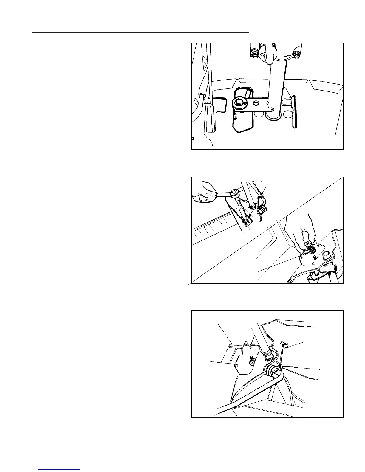
Figure B–9. Adjust Spring Tension
Shift Lever Spring Adjustment
Tension on the shift lever may be increased or de-
creased by adjusting the tension on the shift lever com-
pression spring (K, Figure B–3 Later Model Shift Lever
Assembly). The correct tension for proper shift lever op-
eration should be obtained when the adjustment locknut
(I, Figure B–3) is torqued to 75 - 100 in./lbs.
1. Using a 1/2 deep socket with a 4" - 6" extension bar,
remove the tension adjustment locknut and compres-
sion spring (Figure B–9). Inspect spring and sur-
rounding parts for signs of wear or breakage, and re-
place as needed.
2. Reassemble parts in position as shown in Figure
4B–4, and torque to 75 - 100 in./lbs.
Figure B–10. Disengage Torsion Spring
Shift Lever Replacement
1. Release tension on the shift lever by disengaging the
torsion spring’s (E, Figure B–3) hooked end from the
shift lever shaft. (Figure B–10)
Torsion
Spring
Tension Spring
Tension Spring
 Loading...