6 General Repair
6B Hand Controls Repair
6 - 22
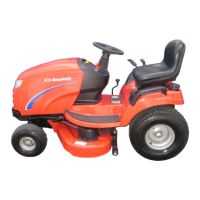
Figure B–11. Remove End Cotter Pin
2. Using a long-nose pliers, remove the cotter pin from
the end of the shift lever. (Figure B–11)
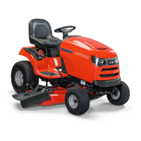
Figure B–12. Slide Shift Lever Out Of Mounting
3. Slide the shift lever out of the shift lever mounting
bushings, and inspect for damage. (Figure B–12)
Replace as necessary.
4. Apply a light application of grease to the end of the
shift lever before reinstalling it into the plastic mount-
ing bushings.
5. Secure the shift lever in place with the cotter pin, and
re-engage the hooked end of torsion spring to the
shift lever.
6. Check the shift lever for smooth operation.
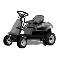
Figure B–13. Shift Lever Assembly Removal
Shift Lever Assembly Replacement
The shift lever assembly should be replaced if damaged
or worn.
1. Remove the steering wheel and steering shaft. See
Steering Wheel Removal and Steering Shaft
Removal sections.
2. From the underside of the unit, remove the two steer-
ing gear adjustment locknuts (Figure B–13) that se-
cure the steering mounting plate and lower nylon
bushing to the frame. Removal of the locknuts allows
the two mating carriage bolts to be removed from the
inside, near the base of the shift lever assembly.
3. Disassemble the shift lever and related parts as pre-
viously shown in the Shift Lever Service section.
Cotter Pin
Shift Lever
 Loading...