6 - 23
6 General Repair
6B Hand Controls Repair
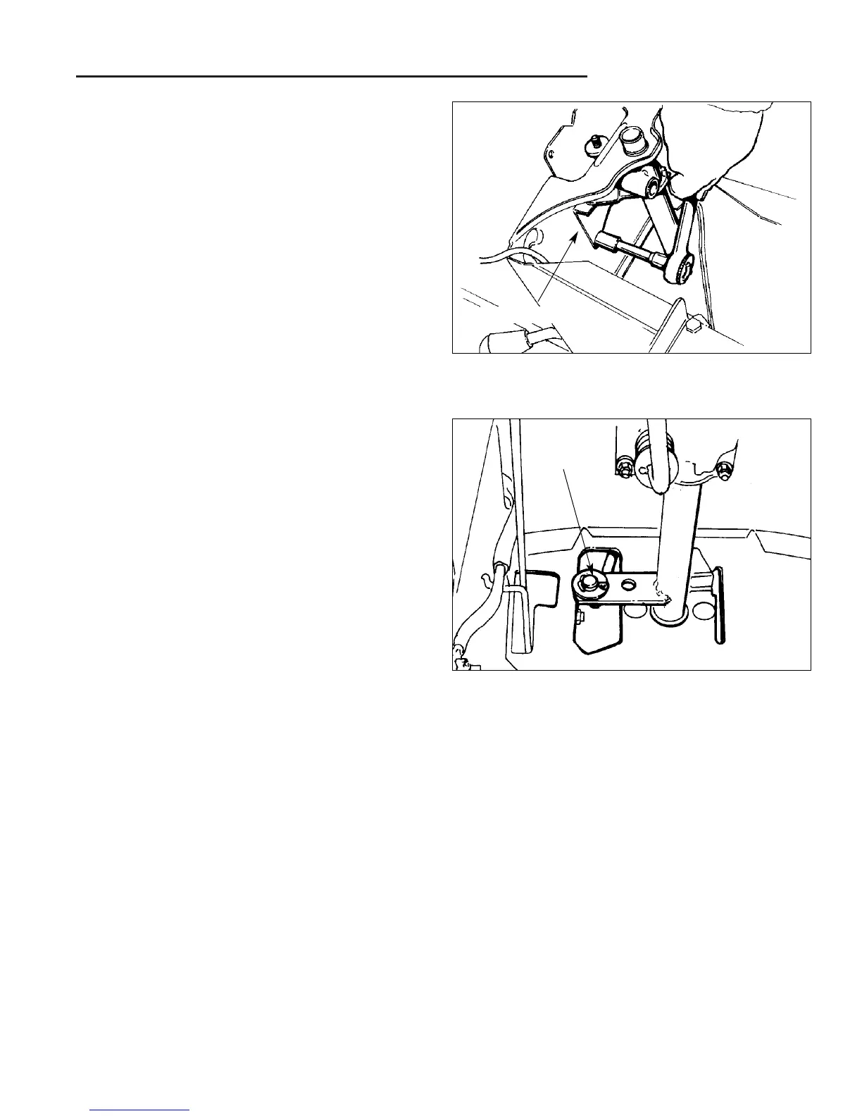
Figure B–14. Disassemble Tension Bracket From
Lower Dash
4. Using a 7/16" socket and a short extension bar, re-
move the two sets of hex nuts, lockwashers, flat
washers, and carriage bolts that attach the tension
bracket to the inside wall of the lower dash (Figure
B–14).
Figure B–15. Disconnect Shift Rod Linkage From
Shift Lever Assembly Arm
Cotter Pin
Tension Bracket
5.Remove the cotter pin connecting the shift lever as-
sembly arm to the front transmission shift rod linkage
(Figure B–15).
6. The shift lever assembly may now be removed from
the unit and inspected for wear or damage. Replace
parts as required. Refer to Figure B–3 for proper as-
sembly sequence of parts.
7. Reassemble parts in reverse order of disassembly.
Apply a light coating of grease to the inside diameter
of all bushings before reinstalling the shift lever as-
sembly in the unit.
NOTE: On later models with adjustable tension, attach
tension bracket (S, Figure B–3) against lower dash be-
fore tightening hex nut (L) on stud (P). Adjust tension on
adjustment nut (I) to 75 - 100 in./lbs.
8. If no additional service is to be performed in this area,
reassemble dash and related parts in reverse order
of disassembly.
9. If lift lever parts are to be serviced, proceed to the Lift
Lever Assembly Service section.
 Loading...