6 General Repair
6A Steering & Front Wheel Repair
6 - 4
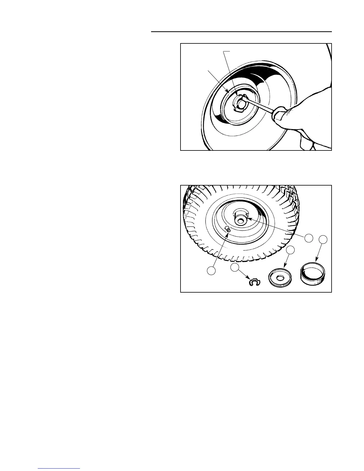
Figure A–3. Front Wheel Retaining Ring - Broadmoor
Front Wheel Repair
BROADMOOR MODELS
NOTE: Illustrations show AGCO Allis, Massey-Ferguson,
and earlier Simplicity model style of hubcap and hard-
ware. Later model Simplicity units have a large snap-on
hubcap cover that must be removed for access to the
wheel retaining ring.
1. Using a flat blade screwdriver, pop off the plastic hub
cap to gain access to the retaining ring.
2. Insert the tip of the flat blade screwdriver into the
area at the open end of the retaining ring, and twist
the blade against the retaining ring to force the retain-
ing ring out of the groove (Figure A–3).
3. With the retaining ring partially out of the groove,
insert the blade tip between the retaining ring and
spindle shaft, and pop the retaining ring out of the
groove.
4. Slide the wheel off the spindle shaft (Figure A–4).
Note that the tire air valve and axle grease fitting are
located on the inside of the wheel.
5. Removal of the wheel provides an opportunity to
inspect the inside of the tire for sidewall damage, as
well as to check inflation pressure. Also, visually
check wheel bushings for wear or damage before
reinstalling the wheel on the unit, and replace as
required. Wheel bushings are pressed into the wheel
hub with a press fit and may be removed by pressing
or driving out. Align the flat on the bushing with the
grease fitting before pressing in the bushing. When
installing new bushings, measure the I.D. of the
wheel hub to determine the correct bearing O.D. size.
See inset illustration in Figure A–2 for sizes.
Retaining ring
Hubcap
retainer
Figure A–4. Wheel And Assembly Hardware - Broadmoor
A. Air Valve D. Hubcap Retainer
B. Grease Fitting E. Hubcap
C. Retaining Ring
A
C
B
D
E
 Loading...