6 - 11
6 General Repair
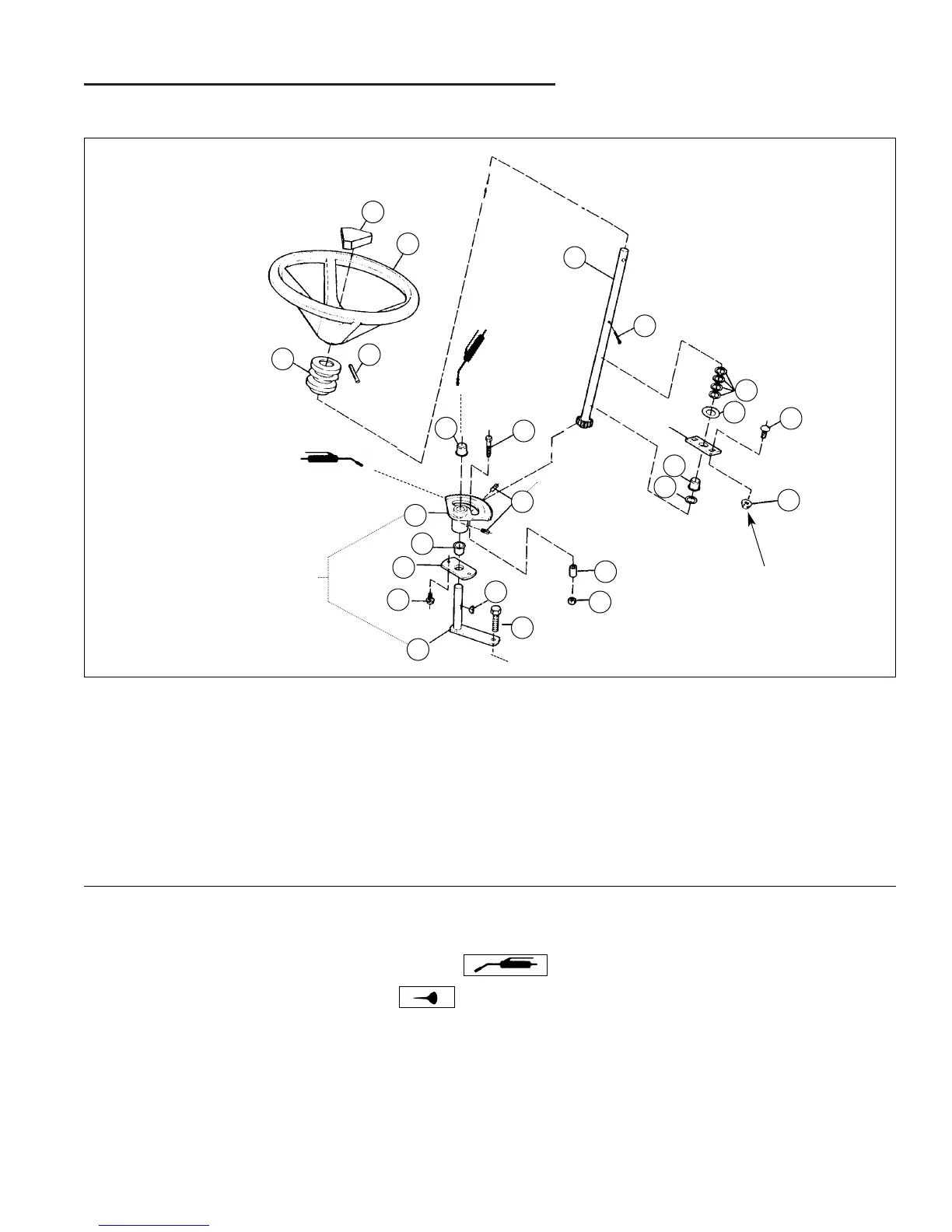
6A Steering & Front Wheel Repair
A. Cap
B. Steering Wheel
C. Pin, 5/16 x 2
D. Tube
E. Steering Shaft
F. Cotter Pin
G. Washer, 49/64
H. Washer
I. Carriage Bolt, 3/8-16 x 1
J. Nut, Flange Lock, 3/8-16
K. Bushing
L. Capscrew, 5/16-18 x 1-1/2
M. Spacer
N. Nut, 5/16-18
O. Capscrew, 3/8-16 x 1-3/8
P. Pitman Arm
Q. Key
R. Screw, Taptite, 5/16-18 x 1
S. Sector Mounting Plate
T. Steering Gear Assy. Hub
U. Square Head Set Screw
UPPER STEERING GROUP ASSEMBLY
I
G
J
K
G
F
E
L
K
T
K
S
R
Q
O
P
N
M
C
D
B
A
NOTE 4
(gear teeth) Apply Loctite
#271. Torque
to 20-30 ft.lbs.
Torque to 17-23
ft.lbs. (2 places)
Early models used a
capscrew, washer & nut
in place of a roll pin (C).
Figure A–18. Upper Steering Assembly
To Rod End - See Figure 4A–8
NOTES:
1. Unless specified, use torque specifications shown on standard hardware torque specification chart.
2. Grease locations indicated by grease gun symbol:
3. Oil locations indicated by oil can symbol:
4. Pitman arm shaft (P) should protrude 9/16" above top of steering gear assembly hub (T).
Grease
bushings "K"
(3 places)
H
U
 Loading...