6 - 27
6 General Repair
6B Hand Controls Repair
BROADMOOR GEAR SHIFT ROD - PEERLESS TRANS.
1. Remove battery from unit to provide access to front
shift lever rod assembly at base of shift lever assem-
bly (See preceding Broadmoor Hydro shift rod ser-
vice section.)
2. Remove cotter pins that secure front shift lever rod to
shift lever arm, and set washers aside for reuse when
reassembling rod.
3. Safely elevate and support unit (mower deck re-
moved) for working access to transmission shift lever
area.
4. See Figure B–26. Remove capscrew, hex nut, wash-
ers and spacers connecting shift rod to shift lever,
and remove shift rod from unit. Inspect shift rod for
wear or damage, and replace as required.
5. Reassemble parts in reverse order of disassembly,
applying grease to pivot points as indicated.
6. Adjust transmission as required for proper operation -
see "Adjustments" section of manual for specific pro-
cedures.
G
F
A
F
C
B
I
D
H
J
I
E
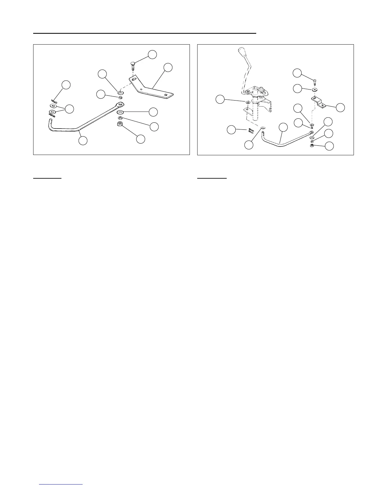
Figure B–26. Broadmoor Gear Shift Rod
Peerless Transmission
Parts List
A. Shift Lever
B. 5/16 Washer
C. 5/16 Lockwasher
D. 5/16-18 Full Hex Nut
E. Spacer
F. Washer
G. 5/16 x 1-1/4 Capscrew
H. Shift Rod
I. 1/2 Washer
J. 3/32 x 3/4 Cotter Pin
Figure B–25. Broadmoor Hydro Shift Rod
Eaton Transmission
Parts List
A. 5/16-18 x 1-1/4 Carriage Bolt
B. Speed Control Lever
C. Spacer
D. Plain Washer
E. 5/16 Lockwasher
F. Full Hex Nut
G. Shift Rod
H. 1/2" Washer
I. Cotter Pin
BROADMOOR HYDRO SHIFT ROD - EATON TRANS.
1. Remove battery from unit to provide access to front
shift lever rod assembly at base of shift lever assem-
bly (See preceding Broadmoor Hydro shift rod ser-
vice section.)
2. Remove cotter pins that secure front shift lever rod to
shift lever arm, and set washers aside for reuse when
reassembling rod.
3. Safely elevate and support unit (mower deck re-
moved) for working access to transmission shift lever
area.
4. See Figure B–25. Remove carriage bolt, hex nut,
washers and spacers connecting shift rod to shift
lever, and remove shift rod from unit. Inspect shift
rod for wear or damage, and replace as required.
5. Reassemble parts in reverse order of disassembly,
applying grease to pivot points as indicated.
6. Adjust transmission as required for proper operation -
see "Adjustments" section of manual for specific pro-
cedures.
I
H
G
A
B
D
C
D
E
F
 Loading...