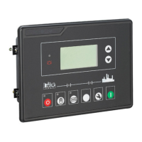
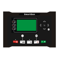
APC715 Pump Unit Controller
APC715 Pump Unit Controller ISSUE 2013-08-28 Version 1.0 Page 12 of 62
4.3 LCD DISPLAY
4.3.1 MAIN DISPLAY
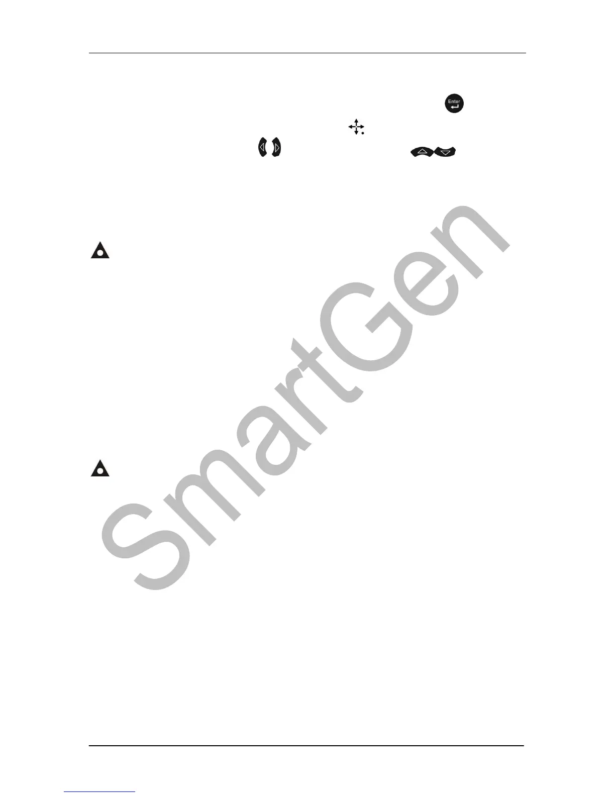
Main screen is divided into left and right separate viewing areas, use to select a
viewing area; the selected area is marked with in its upper left corner. Both
viewing areas show pages; use to scroll the pages and to scroll the
screen.
★Engine, including as below,
Engine status, engine temperature, engine oil pressure, fuel level, Configurable Sensor 1,
battery voltage, charger voltage, accumulated run time, accumulated start times.
NOTE: If connected with J1939 engine via CANBUS port, this page also includes:
coolant pressure, coolant level, fuel temperature, fuel pressure, inlet temperature,
exhaust temperature, turbo pressure, fuel consumption, total fuel consumption and so
on. (Different engine with different parameters)
★Pump Unit:
Outlet pressure, pump flow, pump head, config. sensor 2~6 (can be set as
temperature sensor, pressure sensor or level sensor)
Formula:Pump Head = ( Outlet pressure - Static Pressure)/0.0098.
★Alarm:
Display all warnings, shutdown alarms, trip shutdown alarms and the corresponding
information.
NOTE: For ECU alarms and shutdown alarms, if the alarm information is displayed,
check engine according to it, otherwise, please check the manual of generator according
to SPN alarm code.
◙ Event log
Records all start/stop events (shutdown alarm, trip shutdown alarm, manual/auto start or
stop) and the real time when alarm occurs.
Others, including,
Time and Date, maintenance due time, input/output ports status.
◙ About, including,
Issue time of software and hardware version, product PD number.
 Loading...