EasyManua.ls Logo

Smartgen APC715 User Manual

Smartgen APC715
62 pages
To Next Page IconTo Next Page
To Previous Page IconTo Previous Page
Page #59 background image
APC715 Pump Unit Controller
APC715 Pump Unit Controller ISSUE 2013-08-28 Version 1.0 Page 59 of 62
12.18 VOLVO-EMS2
Volvo Engine types are TAD734, TAD940, TAD941, TAD1640, TAD1641, and
TAD1642.
Terminals of controller
Engine’s CAN port
Remark
Programmable output
1
6
ECU stop
Set programmable output 1 as
“ECU stop”
Programmable output
2
5
ECU power
Set programmable output 2 as
“ECU power”
3
Negative power
4
Positive power
CAN GND
-
CAN communication shielding
line(connect with controllers
terminal only)
CAN(H)
1(Hi)
Impedance 120Ω connecting
line is recommended.
CAN(L)
2(Lo)
Impedance 120Ω connecting
line is recommended.
Engine type: Volvo-EMS2
NOTE: When this engine type is selected, preheating time should be set to at
least 3 seconds.
12.19 YUCHAI
It is suitable for BOSCH common rail pump engine.
Terminals of controller
Engine 42 pins port
Remark
Fuel relay output
1.40
Connect to engine ignition lock
Start relay output
-
Connect to starter coil directly
CAN GND
-
CAN communication shielding
line(connect with controllers
this terminal only)
CAN(H)
1.35
Impedance 120Ω connecting
line is recommended.
CAN(L)
1.34
Impedance 120Ω connecting
line is recommended.
Battery
Engine 2 pins
Remark
Battery negative
1
Wire diameter: 2.5mm
2
Battery positive
2
Wire diameter: 2.5mm
2
Engine type: BOSCH
Question and Answer IconNeed help?

Do you have a question about the Smartgen APC715 and is the answer not in the manual?

Smartgen APC715 Specifications

General IconGeneral
BrandSmartgen
ModelAPC715
CategoryControl Unit
LanguageEnglish

Summary

Clarification of Notation

WARNING!

Alerts to risks of injury or loss of life if procedures are not followed correctly.

4 OPERATION

4.2 PUSHBUTTONS

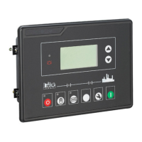
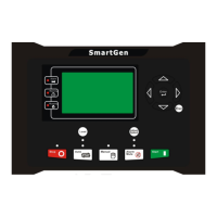
Details the function and operation of each pushbutton on the controller panel.

4.3.2 USER MENU AND PARAMETERS SETTING MENU

Guide to accessing user menus for parameter settings, language, and other configurations.

4.4 AUTO START/STOP OPERATION

Explains the automatic start and stop sequences for the pump unit.

4.5 MANUAL START/STOP OPERATION

Details the procedures for manual start and stop operations of the pump unit.

4.6 ON-LOAD CONTROL PROCESS

Describes how the pump unit engages and disengages load in different operational modes.

4.7 ADJUST SPEED CONTROL

Explains methods for adjusting engine speed to control pump unit output pressure.

5 PROTECTION

5.1 WARNINGS

Lists all warning conditions that alert the operator without stopping the unit.

5.2 SHUTDOWN ALARM

Details all shutdown alarm types that cause the unit to stop and require manual reset.

5.3 TRIP SHUTDOWN

Describes shutdown conditions that initiate a cooling delay before engine shutdown.

5.4 FAULT IDLE

Explains fault idle conditions that trigger a cooling delay before idle running.

7 DEFINITION AND RANGE OF PARAMETERS

7.1 PARAMETER CONTENTS AND RANGE (TABLE 1)

Defines timer and engine settings, their parameters, default values, and descriptions.

7.5 CONDITIONS OF CRANK DISCONNECT SELECTION

8 PARAMETERS SETTING

12 CONNECTIONS OF CONTROLLER WITH J1939 ENGINE

14 FAULT FINDING

Related product manuals