HRX-OM-W002-A
Chapter 3 Transport and Setting Up
3.3 Installation
HRR Series
3.3.4 Contact input/output communication wiring
The product has a contact input/output communication function as shown
below. Connect cables referring to the applicable chapter for each function.
(For details of the functions, refer to Operation Manual Communication
Function.)
Run/Stop input・Remote signal input (Refer to “3.3.5 Wiring of
run/stop signal input and remote signal input”)
Output of contact output signal (Refer to “3.3.6 Wiring of contact
output signal Wiring of contact output signal”))
Use the signal cable described below for wiring of each function.
Contact Input/Output communication connector
The following connectors are used for this product as a contact input / output
signal connector. Please prepare suitable mating connector cable.
Table 3-4 Contact input/output communication connector
Connector specification (this product side)
Dsub 15 pin female (socket) type
Table 3-5 Contact input/output communication specification
*1 : When using the power supply of this product, make sure that the total load current is 500 mA or
less.
*2 :Refer to "3.3.6 Wiring of contact output signal"。
・ Run/Stop signal
・ External switch signal
Contact
output
signal
1,2,3
AC48V or less /DC30V or less
・ Signal of operating status
・ Signal for the alarm status
・ Signal for completion of
preparation
(TEMP READY) etc 2
AC/DC 500mA(Resistance
load)
DC24V±10% 500mA MAX 1
(It can not be used for inductive load.)
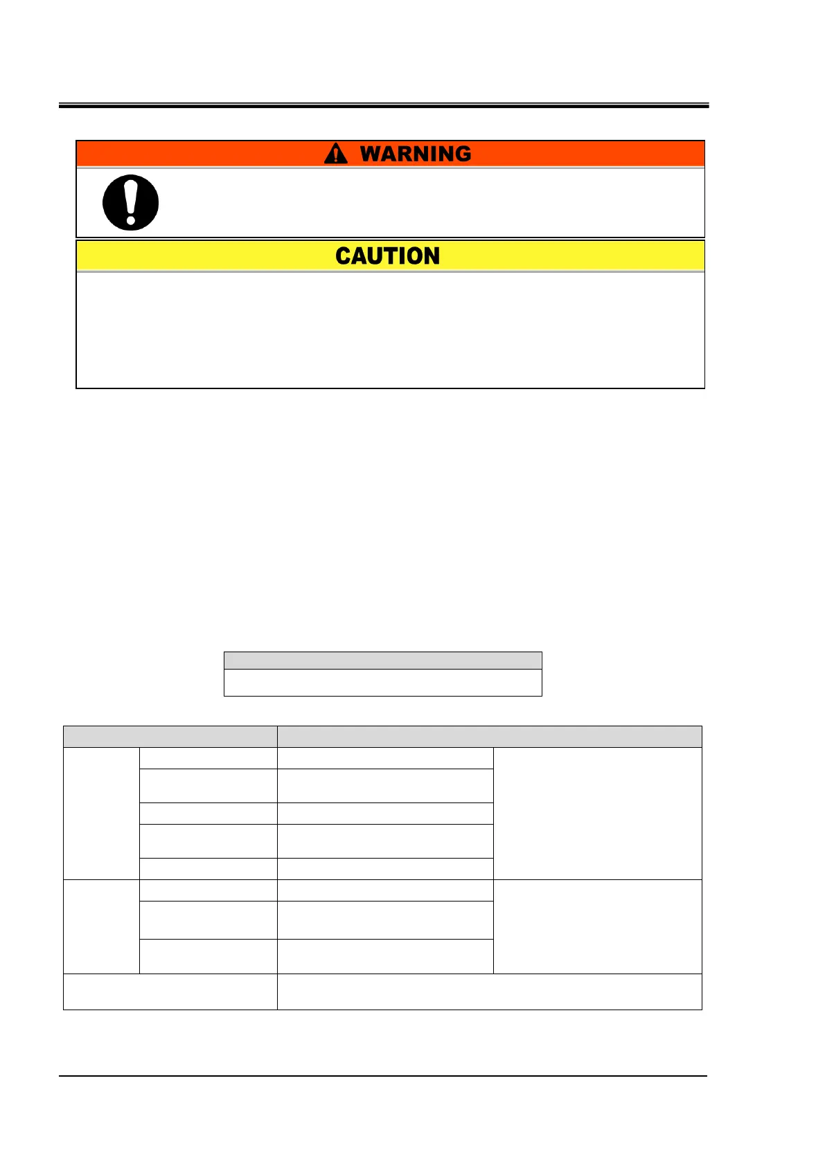
Be sure to lock out and tag out the breaker of the facility power supply
(the user’s machine power supply) before wiring.
Use a connector that is specified.
The capacity of the output contact of the product is limited. If the capacity is not
large enough, install a relay, etc. (to allow for larger capacity). Also, ensure that the
input current of the relay is small enough in relation to the contact capacity of the
product.

 Loading...