HRX-OM-W002-A
Chapter 3 Transport and Setting Up
3.3 Installation
HRR Series
3.3.8 RS-232C communication wiring
Serial communication RS-232C, operation start/stop, setting and reading of
circulating fluid temperature, and reading of alarm condition can be
performed by remote control.
Refer to Operation Manual “Communication Function” for more details.
RS-232C communication connector
The following connector is used for this product as RS-232C communication
connector.Please prepare suitable mating connector.
Table 3-9 RS-232C communication connector
Connector specification (this product side)
Dsub 9 pin female (socket) type
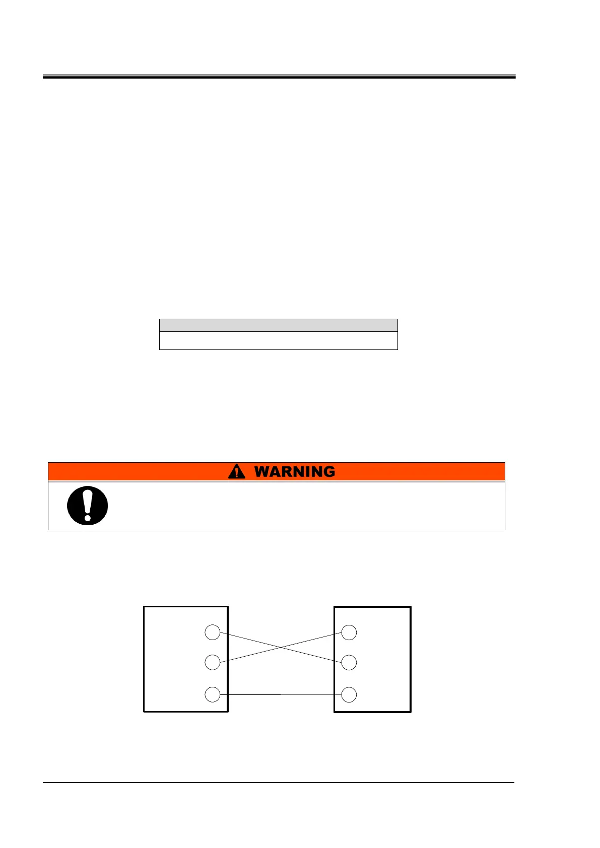
Wiring of communication cable
Be sure to wire as shown in the figure below.
Configuration
One thermo-chiller for one master.
Fig. 3-8 Connection of RS-232C
2
3
5
RD
SD
SG
2
3
5
RD
SD
SG
Master This product
Be sure to turn OFF the breaker of the facility power supply (the
user's machine power supply) before wiring.

 Loading...