ASC
485
OFF
PROT
TYPE
TERM
1
192
SPEED
T01
DI N1
ALT
INP1
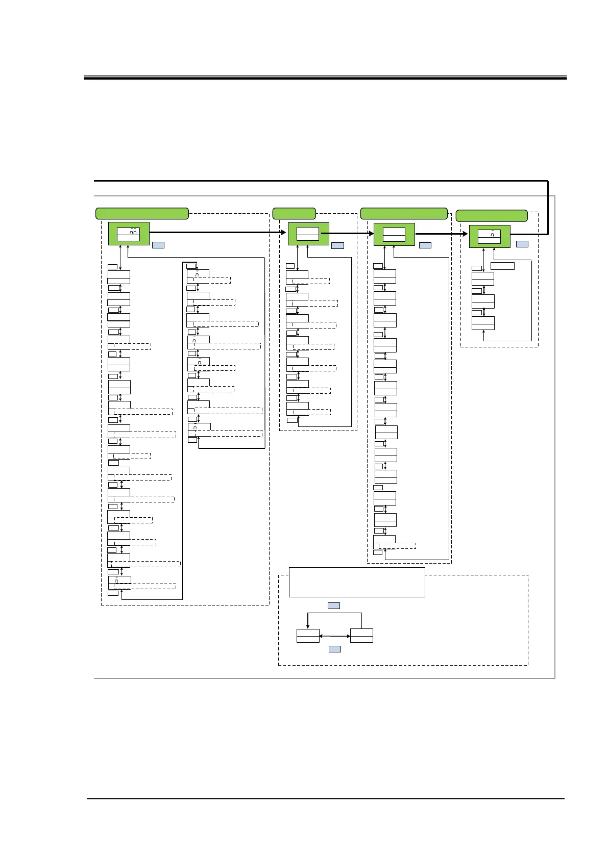
Serialprotocol
Communication
specifications
Slave address
Communication speed
RS-485terminal
Digital input signal 1
Selective Maintenance
▲/▼
▲/▼
▲/▼
▲/▼
▲/▼
▲/▼
▲/▼
▲/▼
MENU
OFF
INP2
ALT
INP2
A
INP2
A
OU T1
Digital input
signal 2
operation
Digital output signal 1
operation
Digital input signal 2
function selection
Digital input signal 2 type
▲/▼
▲/▼
▲/▼
▲/▼
A
INP1
Contact inputsignal 1
operation
▲/▼
DI N2 ⇔ SEL
DOUT1 ⇒ TYPE
SLV ⇔ ADDR
NO
MODE
Setting date reset
RST
MENU
MENU
ALL ⇔ RESET
Communication setting menu
Reset menu
R T
OU T2
OU T2
AL01
OU T2
AL
OU T3
B
OU T3
AL01
OU T3
Digital output 2
selected alarm
Digital output signal 3
selected alarm
Digital output signal 2
function selection
Digital output signal 2
operation
Digital output signal 3
function selection
Digital output signal 3
operation
▲/▼
▲/▼
▲/▼
▲/▼
▲/▼
▲/▼
DOUT2 ⇔ SEL
DOUT2 ⇔ TYPE
DOUT3 ⇔ SEL
DOUT3 ⇔ TYPE
▲/▼
0
Operation time
Pump operation time
Accumulated operation time
of the dust-proof filter
Accumulated operation
time of the DI filter 1
DI T
0
RUNT
0
PUMPT
0
COMPT
0
FLTRT
▲/▼
▲/▼
▲/▼
▲/▼
▲/▼
Compressor
operation time
0
FANT
▲/▼
Fan operation time
*Air-cooled type only
I NFO
MENU
Information moniter menu
00
PGVER
Program version
▲/▼
0000
PGNO
Program number
▲/▼
▲/▼
Contact input signal 2
Delay timer
Changing of
communication error
monitoring alaarm
Changing of
maintenance alarm
MENU
Digital input
signal 1 type
Changing of contact
input signal 2 detection
alarm
Contact input signal 1
OFF Detection timer
Changing of contact
input signal 1 signal
detection
OU T1
RUN
Digital output signal 1
function selection
▲/▼
DOUT1 ⇒ SEL
OU T1
AL01
Digital output signal 1
selected alarm
DI N1 ⇒ SW ⇒ TYPE
DI N1 ⇒ CON ⇒ TYPE
DI N2 ⇒ SW ⇒ TYPE
DI N2 ⇒ CON ⇒ TYPE
DOUT1 ⇒ ALARM ⇒ CODE
A
▲/▼
DOUT2 ⇒ ALARM ⇒ CODE
OU T1
T01
Digital output 2
selected maintenance
DOUT2 ⇒ MANT ⇒ CODE
OU T1
T01
Digital output 3
selected maintenance
DOUT3 ⇒ MANT ⇒ CODE
DOUT3 ⇒ ALARM ⇒ CODE
▲/▼
▲/▼
Unused
DOUTI ⇒ MANT ⇒ CODE
The monitoring time of
communication error
Time when only pump
rus when alarm is
generated
Temp when only pump
rus when alarm is
generated
aAL h
nnn
Alarm history menu
MENU
AL17
Alarm
(The latest)
▲/▼
OFF
DI NI
▲/▼
Digital input signal 1
function selection
hRR
018-R
Model
▲/▼
20-
DMTU
Power Options
▲/▼
Example
AL10
Alarm
▲/▼
ALNN
Alarm
(The oldest)
▲/▼
*1:With electric conductivity
control function only
0
Number of times of
momentary power failure
POWF
▲/▼
NO
NO
PROT
Reset of dust-proof
filter operation time
DI filter
Reset usage time
▲/▼
▲/▼
FLTRT ⇒ RESET
DI T ⇒ RESET
▲/▼
NO
PROT
Reset of pump
operation time
▲/▼
PUMPT ⇒ RESET
NO
PROT
Reset of compressor
operation time
▲/▼
COMPT ⇒ RESET
NO
PROT
Reset of fan
operation time
▲/▼
FANT ⇒ RESET
OFF
Forced DI solenoid
valve
open
DI ⇒ VALVE
0000
instantaneous power failure
occurrence count
DI T
▲/▼
▲/▼
▲/▼
CO
MENU
STD
WS001
standard product/
special numbers
▲/▼
SELIAL.NO
*2
By pressing the ENT key on each alarm history screen,
accumulated operating time and the number of
historcases at the time of occurrence are displayed.
AL10
123
NO2
MENU
ENT
Accumulated operating time at alarm accurrence is displayed
Alarm log number
COMM ⇒ STUS

 Loading...