78
HCD-DX375
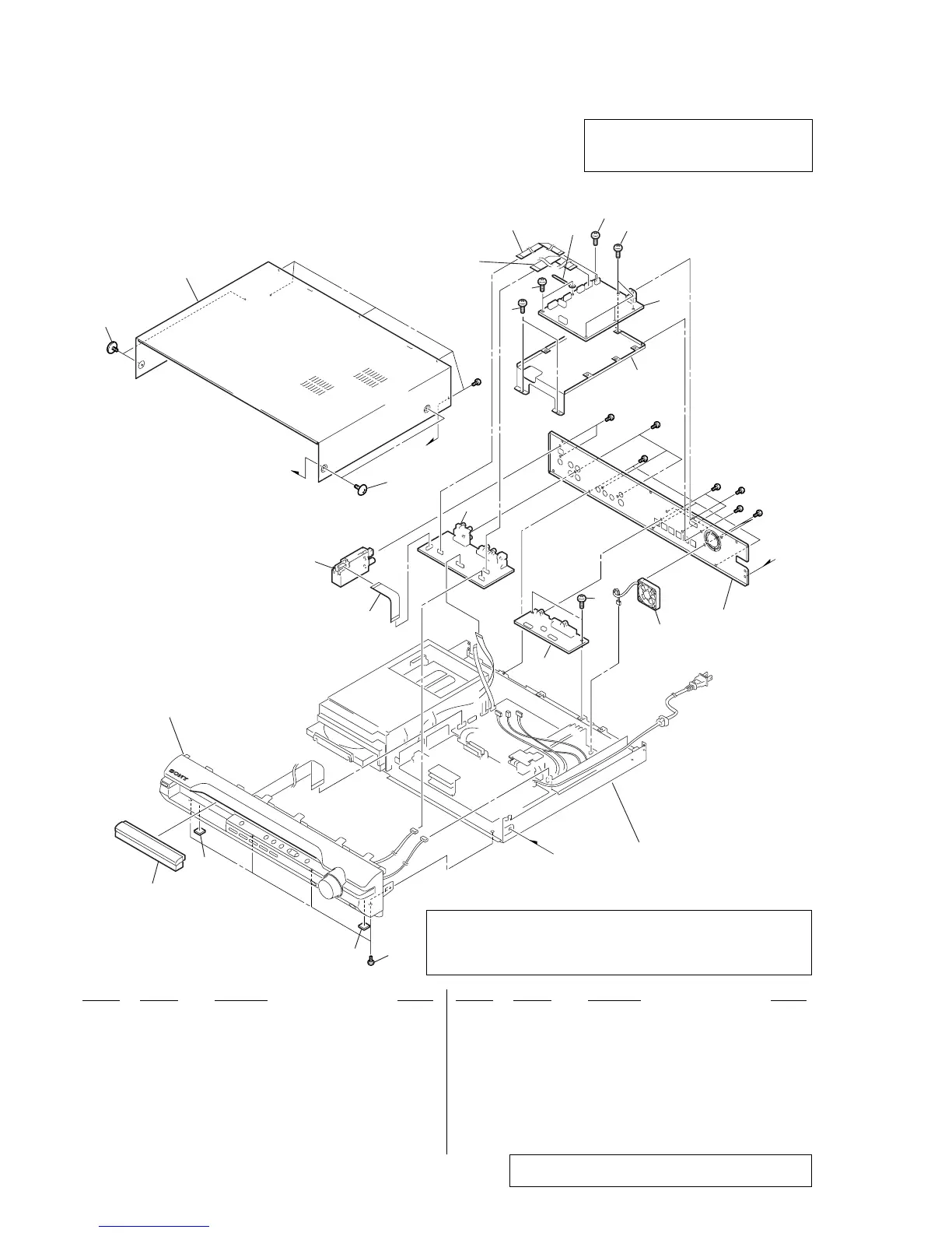
SECTION 7
EXPLODED VIEWS
NOTE:
• -XX and -X mean standardized parts, so they
may have some difference from the original
one.
• Items marked “*” are not stocked since they
are seldom required for routine service.
Some delay should be anticipated when
ordering these items.
• The mechanical parts with no reference
number in the exploded views are not supplied.
Ref. No. Part No. Description Remark Ref. No. Part No. Description Remark
7-1. OVERALL SECTION
1 2-653-086-01 PANEL, LOADING
2 4-232-478-41 FOOT
3 3-077-331-21 +BV3 (3-CR)
4 1-828-953-11 WIRE (FLAT TYPE) (9 CORE)
5 1-693-703-11 TUNER (FM/AM) (TM10SU)
6 A-1176-128-A I/O BOARD, COMPLETE
7 3-363-099-51 SCREW (CASE 3 TP2)
8 2-653-945-01 CASE
✩ 9 A-1148-813-A DMB12 BOARD, COMPLETE
10 1-787-331-11 FAN, D.C.
11 1-828-292-11 WIRE (FLAT TYPE) (5 CORE)
12 1-828-319-11 WIRE (FLAT TYPE) (11 CORE)
#1 7-685-646-79 SCREW +BVTP 3X8 TYPE2 IT-3
#3 7-685-881-09 SCREW +BVTT 4X8 (S)
#5 7-685-871-01 SCREW +BVTT 3X6 (S)
#9 7-682-547-04 SCREW +B 3X6
Note: If the wire (flat type) was replaced, fold it some as the
wire (flat type) before replacement.
The components identified by mark 0 or
dotted line with mark 0 are critical for safety.
Replace only with part number specified.
#1
#1
#5
#1
#1
#9
#3
b
a
a
7
8
7
5
#1
not
supplied
not
supplied
front panel section
chassis section
10
4
1
2
2
3
b
6
9
11
3
3
not
supplied
not
supplied
3
3
3
12
✩ New part of EEP ROM (IC103, IC706) on the DMB12 board cannot be used.
Therefore, if the mounted DMB12 board (A-1148-813-A) is replaced,
exchange new EEP ROM (IC103, IC706) with that used before the
replacement.
 Loading...