STR-ZA5000ES
14
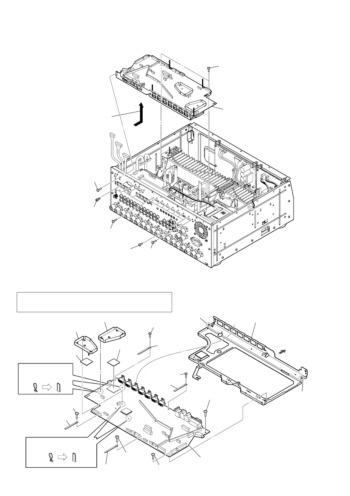
2-8. DIGITAL BOARD BLOCK-2
2-9. DIGITAL BOARD
2 seven screws
(B3 u 5)
6 DIGITAL board block
1 screw
(BV3 u 8CU)
1 screw
(BV3 u 8CU)
3 two screw nuts
– Rear view –
5 Remove the DIGITAL board block
in the direction of the arrow.
1 four screws
(BV3 u 8CU)
4 two screws
(BVTP3 u 8)
3
boss
4
bracket (4F digital (Z5)) block
6
HDMI heat sink
6
HDMI heat sink
7
radiation sheet
7
radiation sheet
8
DIGITAL board
5 Bent two claws are returned
to a straight form.
1
screw
(BV3
u
8CU)
1
screw
(BV3
u
8CU)
2 clamp
1
screw
(BV3
u
8CU)
1
screw
(BV3
u
8CU)
1
screw
(BV3
u
8CU)
2 clamp
2 clamp
3
bos
1
screw
(BV3
u
8CU)
2 clamp
5 Bent two claws are
returned to a straight
form.
rear side
Note: When the complete DIGITAL board is replaced, refer to “CHECKING
METHOD OF WIRED LAN CONNECTION” and “NOTICE OF MAC
ADDRESS CHANGE TO CUSTOMERS” on page 4.
 Loading...