ZS-X3CP
1717
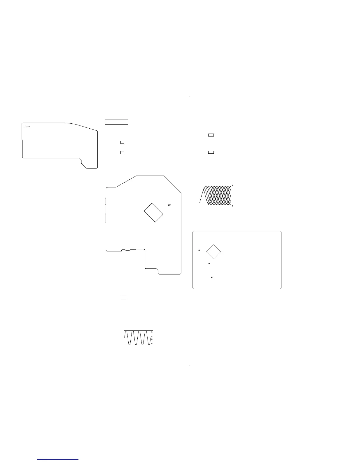
– CONTROL BOARD (Conductor Side) –
IC801
TAP
(TEST)
CD SECTION
Perform all CD section check in the test mode.
HOW TO THE SET INTO CD TEST MODE
1. Press the [POWER] button to turn the power on.
2. Press the x button.
3. Set test mode by momentarily shorting both of TAP (TEST)
on the CONTROL board.
4. Press the x button to enter the CD test mode.
5. To release the CD test mode, press the [POWER] button to
turn the power off.
Checking Location:
TRAVERSE CHECK
1. Connect an oscilloscope to TP (TE) and TP (VC) on the
CDMP3 board.
2. Insert the disc (YEDS-18). (Part No.: 3-702-101-01) (CD)
3. Press the u button three times.
4. Confirm that the center of the oscilloscope waveform is at 0 V.
5. Confirm that the oscilloscope waveform Vp-p value is at 0.8 ±
0.2 V.
6. Insert the disc (TCD-W082L). (Part No.: J-2502-063-2) (CD-
RW)
7. Perform confirmation in the same manner as step 4 and 5.
FOCUS BIAS CHECK
1. Connect the oscilloscope to TP (RF) and TP (VC) on the
CDMP3 board.
2. Insert the disc (YEDS-18). (Part No. : 3-702-101-01) (CD)
3. Press the u button three times. (LPC ON)
4. Confirm that the oscilloscope waveform is as shown in the
figure below. (eye pattern)
A good eye pattern means that the diamond shape (◊) in the
center of the waveform can be clearly distinguished.
5. Press the u button three times. (LPC OFF)
6. Perform confirmation in the same manner as step 4.
7. Insert the disc (TCD-W082L). (Part No.: J-2502-063-2) (CD-
RW)
8. Perform confirmation in the same manner as step 4 to 6.
• RF signal reference waveform (eye pattern)
Checking Location:
 Loading...